Serializer Click-Platine
Overview
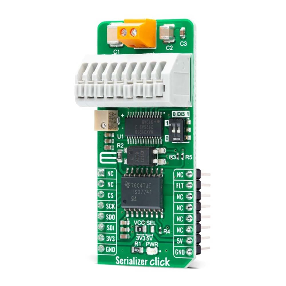
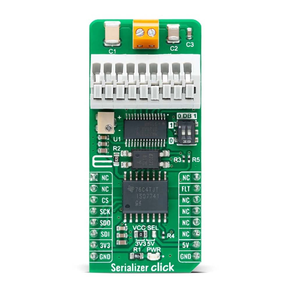
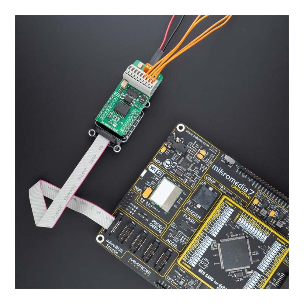
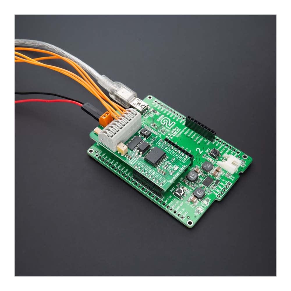
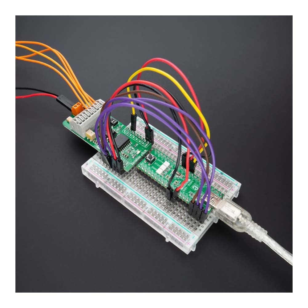
Das Serializer Click Board™ ist eine kompakte Zusatzplatine, die einen digitalen Eingangsübersetzer/Serialisierer enthält. Diese Platine verfügt über den MAX31910, einen achtkanaligen digitalen Eingangsserialisierer für digitale Eingangsmodule mit hoher Kanaldichte in der Industrie- und Prozessautomatisierung von Maxim. Der MAX31910 übersetzt, konditioniert und serialisiert den 24-V-Digitalausgang von Sensoren und schaltet auf 5-V-CMOS-kompatible Signale um, die von der MCU benötigt werden. Er stellt die Front-End-Schnittstellenschaltung eines digitalen Eingangsmoduls einer speicherprogrammierbaren Steuerung (SPS) bereit. Er kommuniziert mit der MCU über die SPI-Schnittstelle und wird in einer Konfiguration mit einem installierten digitalen Isolator geliefert.
Das Serializer Click Board™ eignet sich für verschiedene Anwendungen wie Industrie-, Prozess- und Gebäudeautomatisierung, digitale Eingangsmodule für SPS und mehr.
How Does The Serializer Click Board™ Work?
The Serializer Click Board™ uses the MAX31910, an eight-channel digital input translator/serializer for high-channel density digital input modules in industrial and process automation from Maxim Integrated, now part of Analog Devices. It features integrated current limiting, low-pass filtering, and channel serialization. Input current limiting allows a significant reduction in power consumed from the field voltage supply (external typical 24V) compared to traditional discrete resistor-divider implementations. The device uses patent-pending circuit techniques to further reduce power beyond possible input current limiting alone.
The MAX31910 translates, conditions, and serializes the 24V digital output of sensors and switches to 5V CMOS-compatible signals required by the MCU. It provides the front-end interface circuit of a programmable logic controller (PLC) digital input module. Selectable on-chip low-pass filters allow flexible debouncing and filtering sensor outputs based on the application. The serializer is stackable so that any number of input channels (IN1-IN8) can be serialized and output through only one SPI-compatible port.
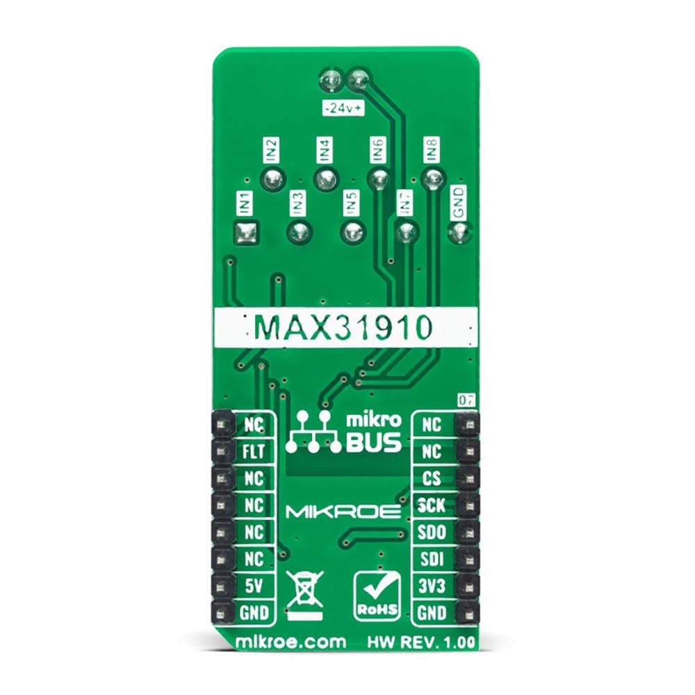
The serializer inputs (IN1-IN8) sense the state (ON vs. OFF) of field sensors by monitoring both voltage and a current flowing through the sensor output. The current sinking through these input pins rises linearly with input voltage until the limit set by the current clamp is reached (set by an onboard potentiometer). Any voltage increase beyond this point does not further increase the input current.
The Serializer Click Board™ communicates with MCU through a standard SPI interface in a configuration with installed digital isolators (ISO7741 and LTV-817S). Also, it uses an interrupt pin, the FLT pin of the mikroBUS™ socket, used as a 'fault' indicator which immediately notifies the host when a fault such as an overtemperature or undervoltage condition occurs. It also has a two-channel switch labelled DB, which determines the current switching frequency. The current switching clock period is automatically selected according to a switch position.
The Serializer Click Board™ can operate with both 3.3V and 5V logic voltage levels selected via the VCC SEL jumper. This way, it is allowed for both 3.3V and 5V capable MCUs to use the communication lines properly. However, the Click board™ comes equipped with a library containing easy-to-use functions and an example code that can be used, as a reference, for further development.
SPECIFICATIONS
Type | Measurements |
Applications | The Serializer Click Board™ be used for various applications such as industrial, process, and building automation, digital input modules for PLCs, and more |
On-board modules | MAX31910 - eight-channel digital input translator/serializer from Maxim Integrated, now part of Analog Devices |
Key Features | Low power consumption, highly integrated, eight channels, robust features and performance for industrial environments, flexible power supply capability, and more |
Interface | SPI |
Compatibility | mikroBUS |
Click board size | L (57.15 x 25.4 mm) |
Input Voltage | 3.3V or 5V,External |
PINOUT DIAGRAM
This table shows how the pinout of the Serializer Click Board™ corresponds to the pinout on the mikroBUS™ socket (the latter shown in the two middle columns).
Notes | Pin | Pin | Notes | ||||
---|---|---|---|---|---|---|---|
NC | 1 | AN | PWM | 16 | NC | ||
NC | 2 | RST | INT | 15 | FLT | Fault Indicator | |
SPI Chip Select | CS | 3 | CS | RX | 14 | NC | |
SPI Clock | SCK | 4 | SCK | TX | 13 | NC | |
SPI Data OUT | SDO | 5 | MISO | SCL | 12 | NC | |
SPI Data IN | SDI | 6 | MOSI | SDA | 11 | NC | |
Power Supply | 3.3V | 7 | 3.3V | 5V | 10 | 5V | Power Supply |
Ground | GND | 8 | GND | GND | 9 | GND | Ground |
ONBOARD SETTINGS AND INDICATORS
Label | Name | Default | Description |
---|---|---|---|
LD1 | PWR | - | Power LED Indicator |
JP1 | VCC SEL | Left | Logic Level Voltage Selection 3V3/5V: Left position 3V3, Right position 5V |
SW1 | DB | - | Current Switching Frequency Selection 1/0: Upper position 1, Lower position 0 |
P1 | - | - | Current Threshold Trimmer |
SERIALIZER CLICK ELECTRICAL SPECIFICATIONS
Description | Min | Typ | Max | Unit |
---|---|---|---|---|
Supply Voltage VCC | 3.3 | - | 5 | V |
External Supply Voltage | 7 | 24 | 36 | V |
Input Data Rate | - | 200 | - | kHz |
Operating Temperature Range | -40 | +25 | 125 | °C |
Software Support
We provide a library for the Serializer Click Board™ as well as a demo application (example), developed using MikroElektronika compilers. The demo can run on all the main MikroElektronika development boards.
The package can be downloaded/installed directly from NECTO Studio The package Manager (recommended), downloaded from our LibStock™ or found on Mikroe Github account.
Library Description
This library contains API for the Serializer Click Board™ driver.
Key functions
-
serializer_get_flt_pin
This function returns the fault pin logic state. -
serializer_read_input
This function reads the input data by using SPI serial interface, and then checks the data integrity by verifying the CRC byte.
Example Description
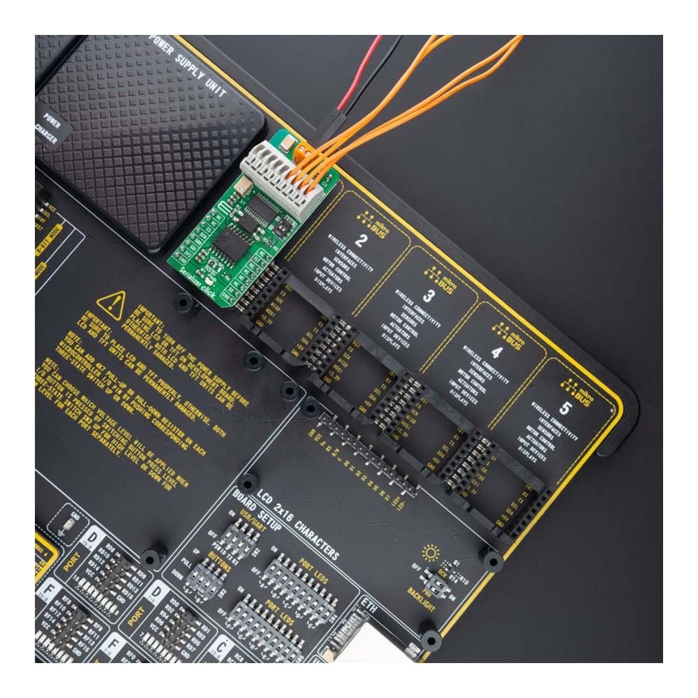
This example demonstrates the use of the Serializer Click Board™ by reading the state of all inputs and displaying the results on the USB UART.
void application_task ( void )
{
uint8_t input_data = 0;
err_t status = serializer_read_input ( &serializer, &input_data );
if ( SERIALIZER_ERROR != status )
{
for ( uint8_t cnt = 0; cnt < 8; cnt++ )
{
log_printf( &logger, " IN%u: %srn", ( uint16_t ) cnt + 1,
( char * ) ( ( input_data & ( 1 << cnt ) ) ? "High" : "Low" ) );
}
if ( status & SERIALIZER_STATUS_UNDERVOLTAGE )
{
log_info( &logger, "Undervoltage fault" );
}
if ( status & SERIALIZER_STATUS_OVERTEMPERATURE )
{
log_info( &logger, "Overtemperature fault" );
}
log_printf( &logger, "rn" );
Delay_ms( 1000 );
}
}
The full application code, and ready to use projects can be installed directly from NECTO Studio The package Manager (recommended), downloaded from our LibStock™ or found on Mikroe Github account.
Other Mikroe Libraries used in the example:
- MikroSDK.Board
- MikroSDK.Log
- Click.Serializer
Additional Notes and Information
Depending on the development board you are using, you may need USB UART click, USB UART 2 Click or RS232 Click to connect to your PC, for development systems with no UART to USB interface available on the board. UART terminal is available in all MikroElektronika compilers.
MIKROSDK
The Serializer Click Board™ is supported with mikroSDK - MikroElektronika Software Development Kit. To ensure proper operation of mikroSDK compliant Click board™ demo applications, mikroSDK should be downloaded from the LibStock and installed for the compiler you are using.
Frequently Asked Questions
Have a Question?
Be the first to ask a question about this.