


Mikroelektronika d.o.o.
Gleichstrommotor 19 Click-Platine
Gleichstrommotor 19 Click-Platine
SKU: MIKROE-4883
Verfügbarkeit für Abholungen konnte nicht geladen werden
Overview
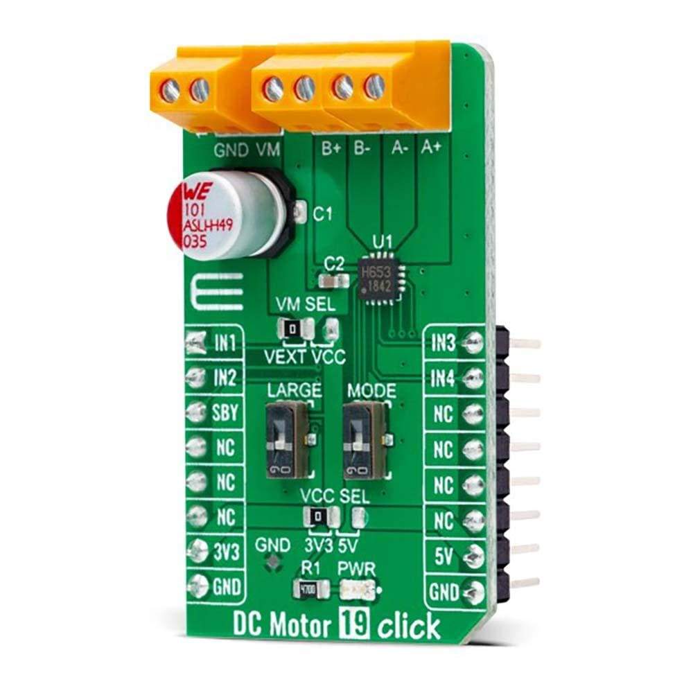
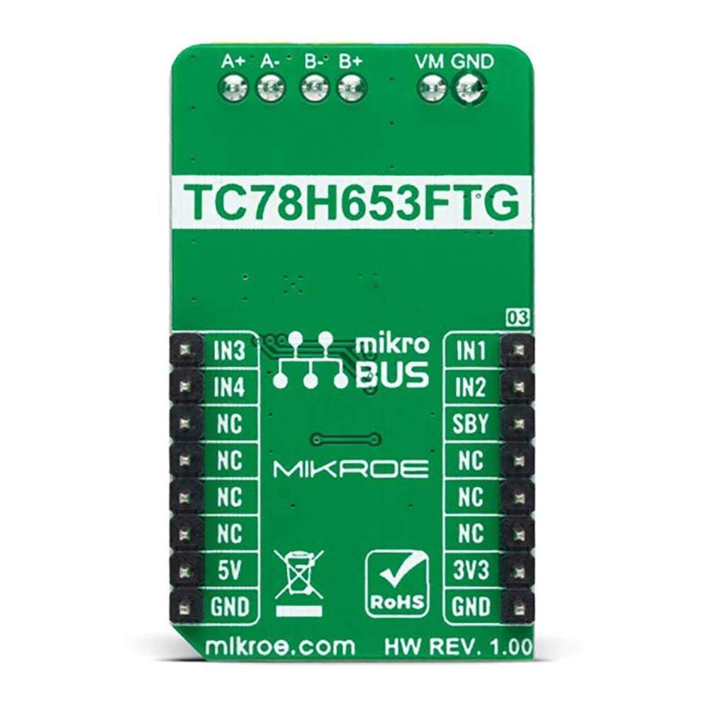
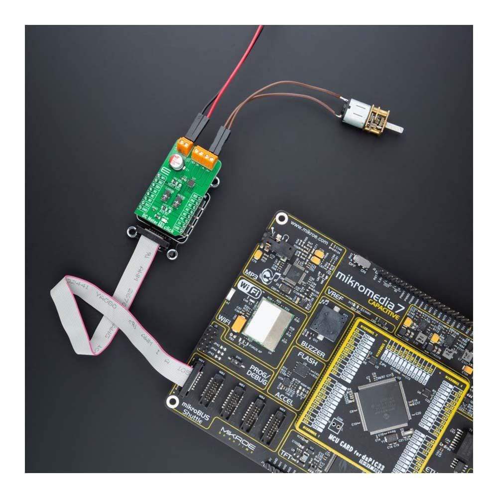
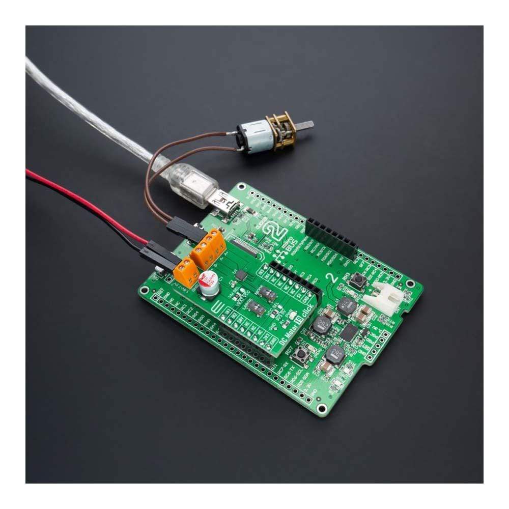
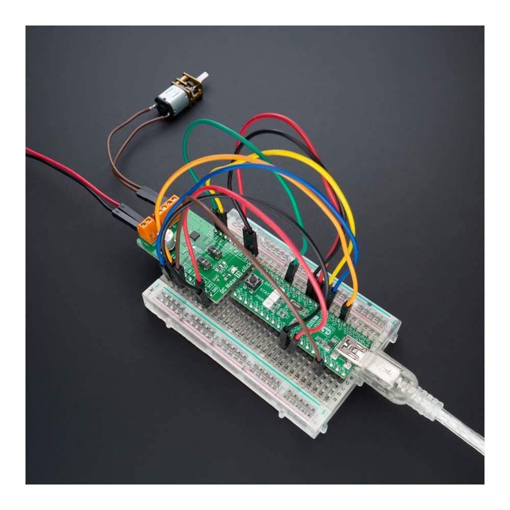
The DC Motor 19 Click Board™ is a compact add-on board that contains a brushed DC motor driver. This board features the TC78H653FTG, a dual H-bridge driver for one or two DC brushed motors or one stepping motor, which incorporates DMOS with low ON resistance in output transistors from Toshiba Semiconductor.
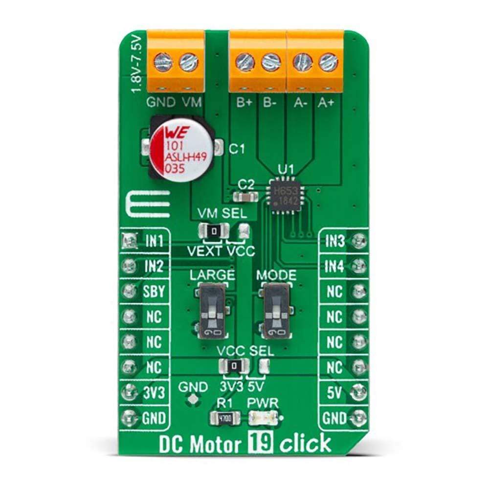
The Forward/Reverse/Brake/Stop mode can be selected according to the state of its input control signals, while the motor operation and current mode can be chosen through onboard switches alongside control signals. It has a wide operating voltage range of 1.8V to 7.5V with an output current capacity of 4A (DC). Besides, it also features built-in protection against under-voltage, overcurrent, and overtemperature conditions.
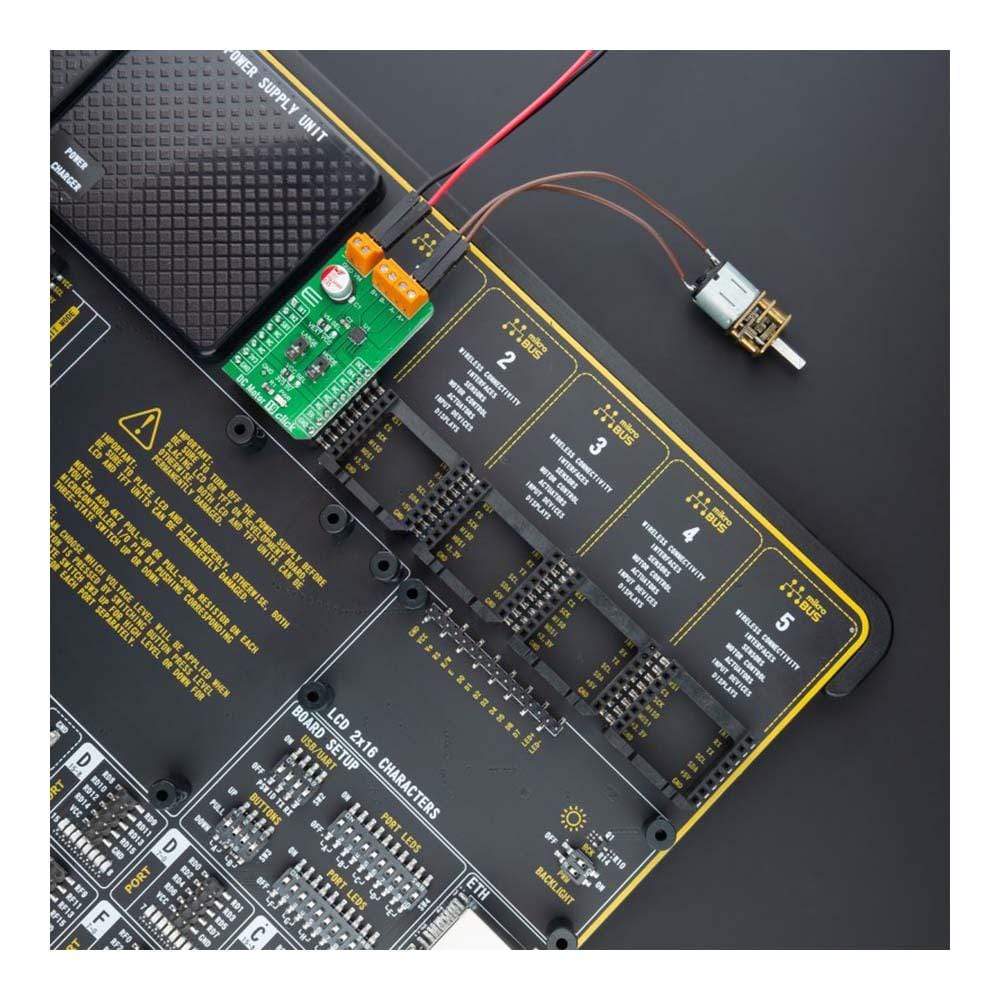
The DC Motor 19 Click Board™ is suitable for driving DC brushed motors and stepping motors for low voltage equipment such as home electronic products and devices using a 5V USB power supply.
Downloads
Der Gleichstrommotor 19 Click Board™ ist eine kompakte Zusatzplatine, die einen Treiber für bürstenbehaftete Gleichstrommotoren enthält. Diese Platine enthält den TC78H653FTG, einen dualen H-Brückentreiber für einen oder zwei bürstenbehaftete Gleichstrommotoren oder einen Schrittmotor, der DMOS mit niedrigem Einschaltwiderstand in Ausgangstransistoren von Toshiba Semiconductor enthält.
Der Vorwärts-/Rückwärts-/Brems-/Stopp-Modus kann je nach Zustand der Eingangssteuersignale ausgewählt werden, während der Motorbetrieb und der Strommodus über integrierte Schalter neben den Steuersignalen ausgewählt werden können. Es verfügt über einen weiten Betriebsspannungsbereich von 1,8 V bis 7,5 V mit einer Ausgangsstromkapazität von 4 A (DC). Darüber hinaus verfügt es über einen integrierten Schutz gegen Unterspannung, Überstrom und Übertemperatur.
Das DC-Motor 19 Click Board™ eignet sich zum Antrieb von Gleichstrom-Bürstenmotoren und Schrittmotoren für Niederspannungsgeräte wie Heimelektronikprodukte und -geräte mit einer 5-V-USB-Stromversorgung.
| General Information | |
|---|---|
Part Number (SKU) |
MIKROE-4883
|
Manufacturer |
|
| Physical and Mechanical | |
Weight |
0.02 kg
|
| Other | |
EAN |
8606027384042
|
Frequently Asked Questions
Have a Question?
Be the first to ask a question about this.