


Mikroelektronika d.o.o.
DC-Motor 21 Click-Platine
DC-Motor 21 Click-Platine
SKU: MIKROE-4877
Verfügbarkeit für Abholungen konnte nicht geladen werden
Overview
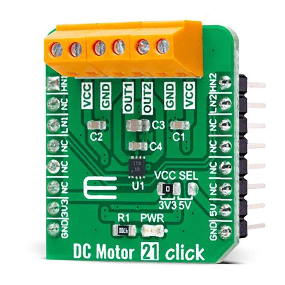
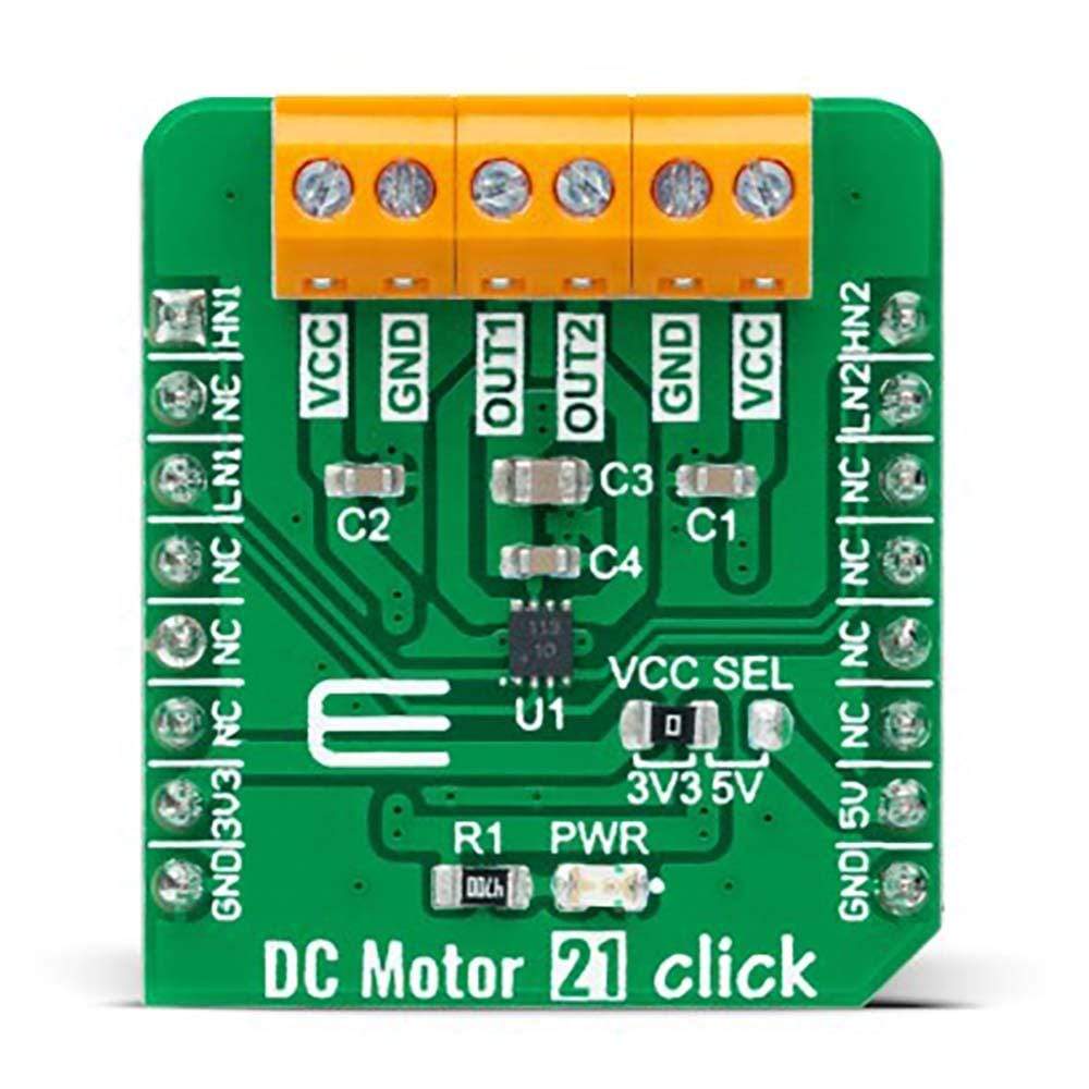
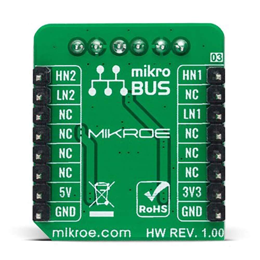
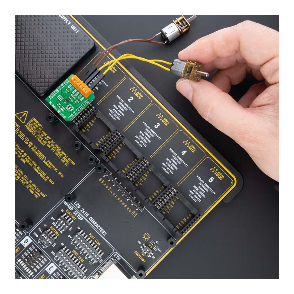
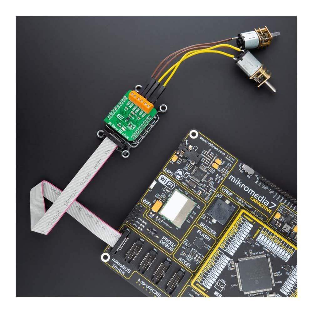
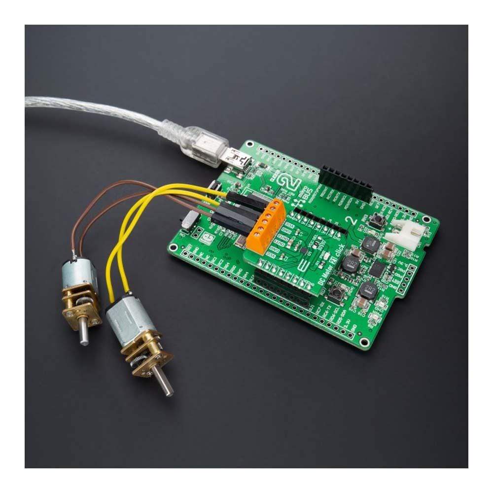
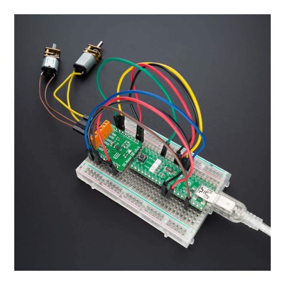
The DC Motor 21 Click Board™ is a compact add-on board that contains a brushed DC motor driver. This board features the A3910, a DC motor driver designed for low voltage power applications from Allegro Microsystems. It is controlled via several GPIO pins and has a wide operating voltage range with an output current capacity of 500mA. In addition to the possibility to be used in the full-bridge configuration to drive a single bidirectional DC motor, it can also be used as a dual half-bridge to drive dual DC motors. Using an integrated MOS switch improves braking action for the motor, compared to implementation with a simple clamp diode. Besides, it also features built-in protection such as crossover current protection and thermal shutdown.
The DC Motor 21 Click Board™ is suitable for driving DC brushed motors and targeted at the consumer and industrial market with end applications to low voltage equipment.
Downloads
Der Gleichstrommotor 21 Click Board™ ist eine kompakte Zusatzplatine, die einen bürstenbehafteten Gleichstrommotortreiber enthält. Diese Platine enthält den A3910, einen Gleichstrommotortreiber von Allegro Microsystems, der für Niederspannungsanwendungen entwickelt wurde. Er wird über mehrere GPIO-Pins gesteuert und verfügt über einen weiten Betriebsspannungsbereich mit einer Ausgangsstromkapazität von 500 mA. Neben der Möglichkeit, ihn in der Vollbrückenkonfiguration zum Antrieb eines einzelnen bidirektionalen Gleichstrommotors zu verwenden, kann er auch als duale Halbbrücke zum Antrieb von zwei Gleichstrommotoren verwendet werden. Die Verwendung eines integrierten MOS-Schalters verbessert die Bremswirkung des Motors im Vergleich zur Implementierung mit einer einfachen Klemmdiode. Darüber hinaus verfügt er auch über integrierte Schutzfunktionen wie Überstromschutz und thermische Abschaltung.
Das DC Motor 21 Click Board™ ist für den Antrieb von Gleichstrommotoren mit Bürsten geeignet und zielt auf den Verbraucher- und Industriemarkt mit Endanwendungen für Niederspannungsgeräte ab.
| General Information | |
|---|---|
Part Number (SKU) |
MIKROE-4877
|
Manufacturer |
|
| Physical and Mechanical | |
Weight |
0.02 kg
|
| Other | |
EAN |
8606027384219
|
Frequently Asked Questions
Have a Question?
Be the first to ask a question about this.