


Mikroelektronika d.o.o.
BATT-MAN 2 Klick-Board
BATT-MAN 2 Klick-Board
SKU: MIKROE-4837
Verfügbarkeit für Abholungen konnte nicht geladen werden


Overview
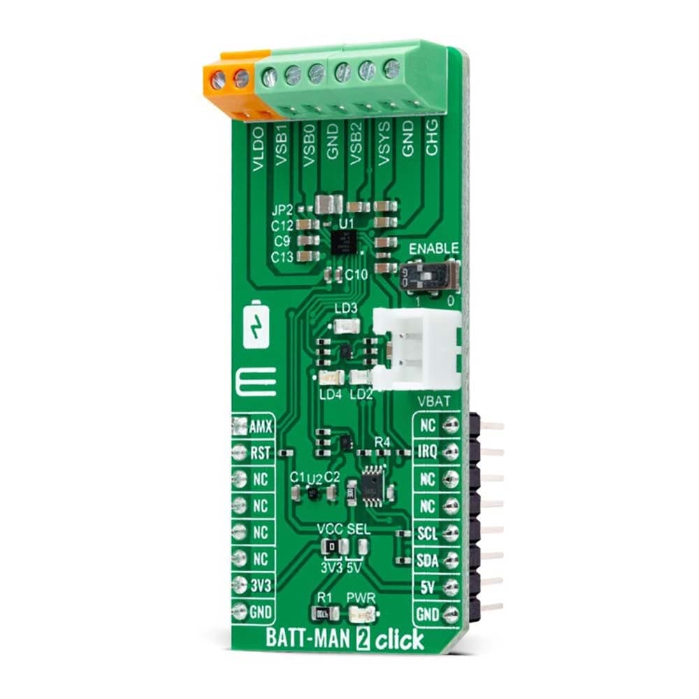
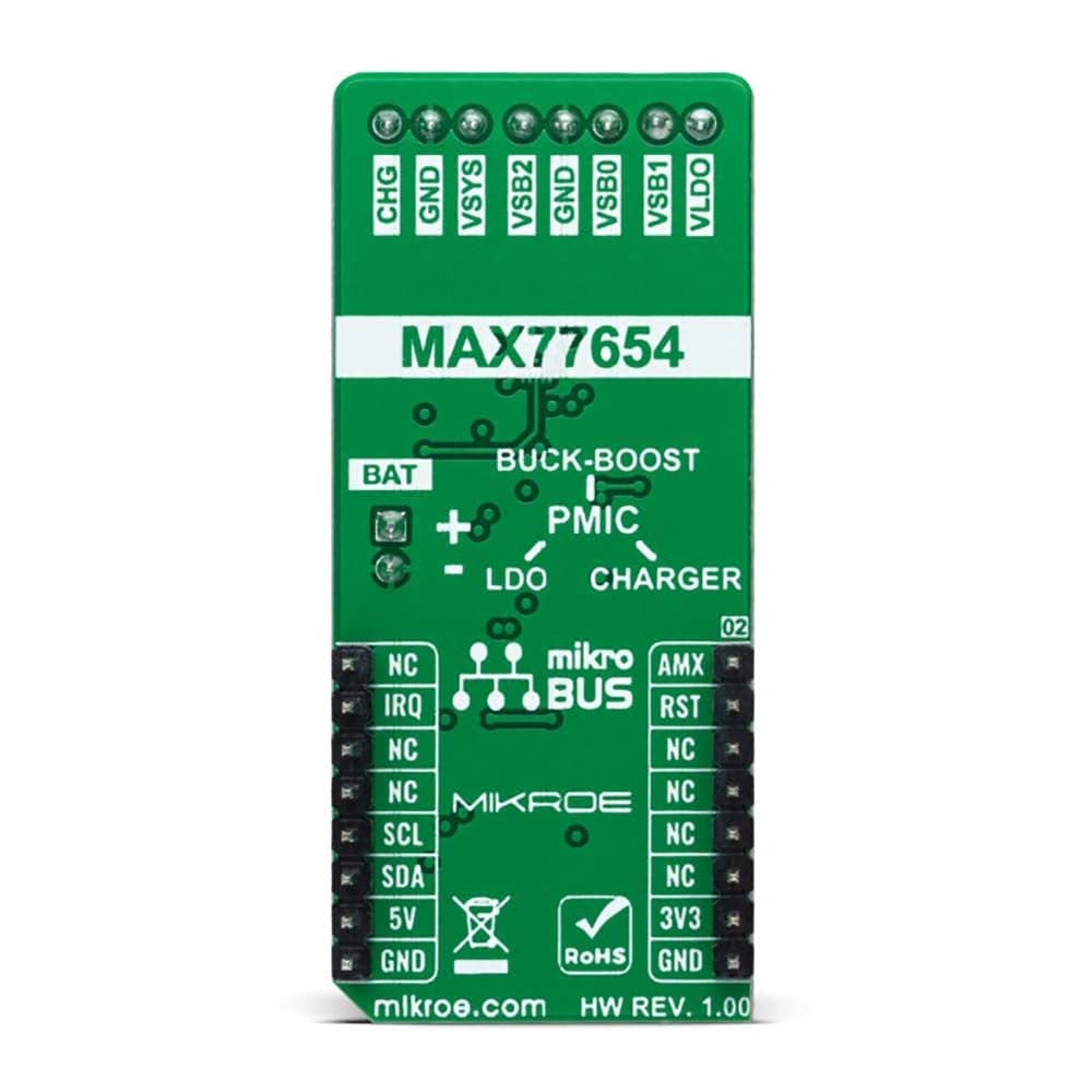
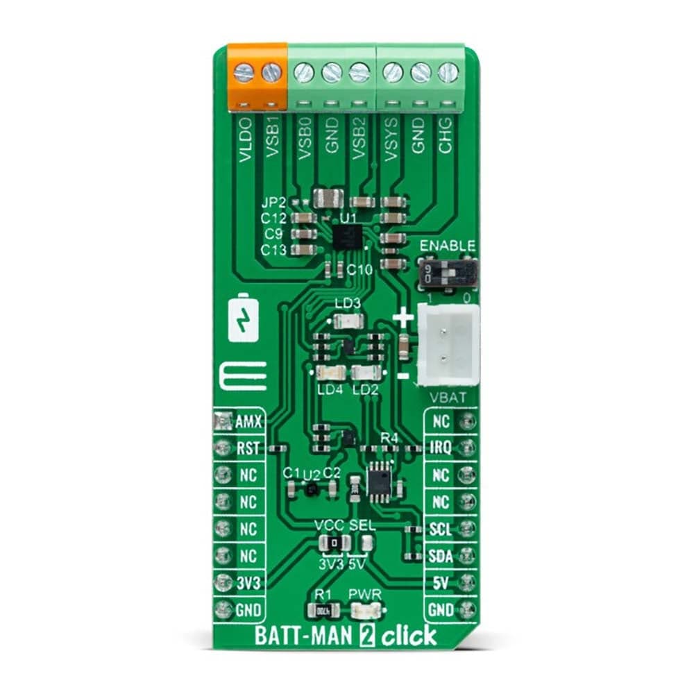
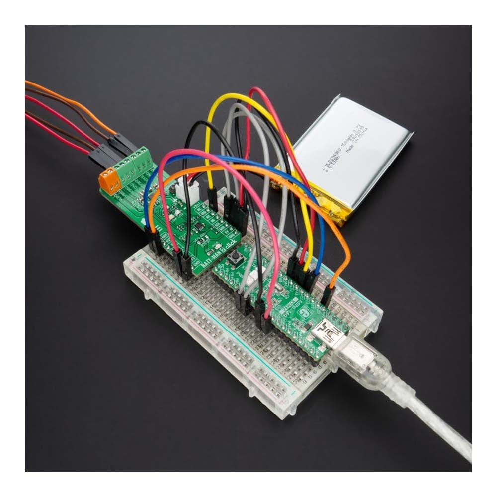
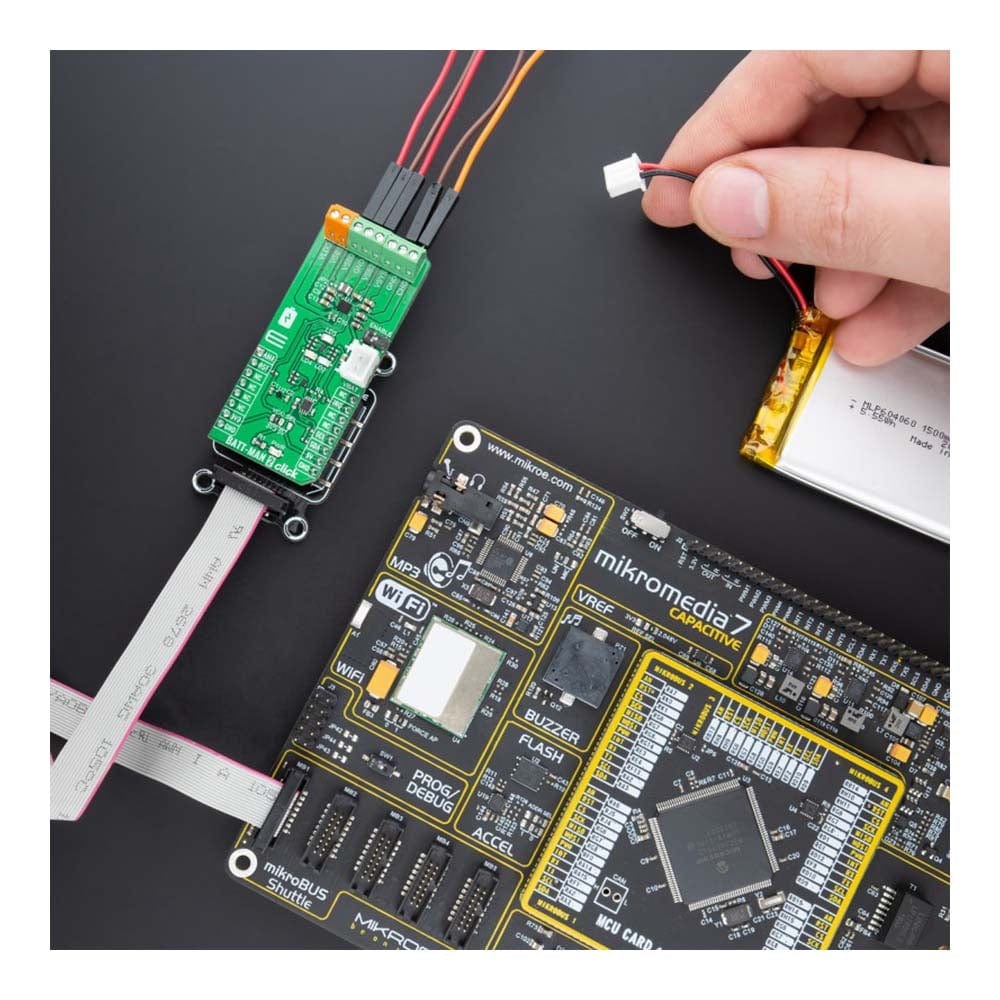
The BATT-MAN 2 Click Board™ is a compact add-on board representing an advanced battery and power management solution. This board features the MAX77654, a single inductor, multiple-output (SIMO) power management IC (PMIC) from Analog Devices. This I2C programmable board features a buck-boost regulator that provides three independently programmable power rails from a single inductor. Also, it has one 100mA LDO output with ripple rejection for audio and other noise-sensitive applications and a highly-configurable linear charger that supports a wide range of Li+ battery capacities featuring battery temperature monitoring for additional safety (JEITA).
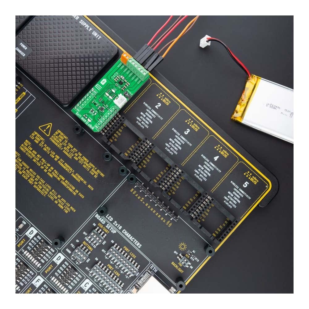
The BATT-MAN 2 Click Board™ is suitable as a battery charging and power supply solution for low-power applications where size and efficiency are critical.
Downloads
Das BATT-MAN 2 Click Board™ ist eine kompakte Zusatzplatine, die eine erweiterte Batterie- und Energieverwaltungslösung darstellt. Diese Platine verfügt über den MAX77654, einen Energieverwaltungs-IC (PMIC) mit einer Induktivität und mehreren Ausgängen (SIMO) von Analog Devices. Diese I2C-programmierbare Platine verfügt über einen Abwärts-/Aufwärtsregler, der drei unabhängig programmierbare Stromschienen von einer einzigen Induktivität bereitstellt. Außerdem verfügt sie über einen 100-mA-LDO-Ausgang mit Welligkeitsunterdrückung für Audio- und andere geräuschempfindliche Anwendungen und ein hochkonfigurierbares lineares Ladegerät, das eine breite Palette von Li+-Batteriekapazitäten unterstützt und über eine Batterietemperaturüberwachung für zusätzliche Sicherheit (JEITA) verfügt.
Das BATT-MAN 2 Click Board™ eignet sich als Batterielade- und Stromversorgungslösung für Anwendungen mit geringem Stromverbrauch, bei denen Größe und Effizienz entscheidend sind.
| General Information | |
|---|---|
Part Number (SKU) |
MIKROE-4837
|
Manufacturer |
|
| Physical and Mechanical | |
Weight |
0.02 kg
|
| Other | |
EAN |
8606027389801
|
Frequently Asked Questions
Have a Question?
Be the first to ask a question about this.