


Mikroelektronika d.o.o.
ISM RX 3 Click-Platine
ISM RX 3 Click-Platine
SKU: MIKROE-4828
Verfügbarkeit für Abholungen konnte nicht geladen werden


Overview
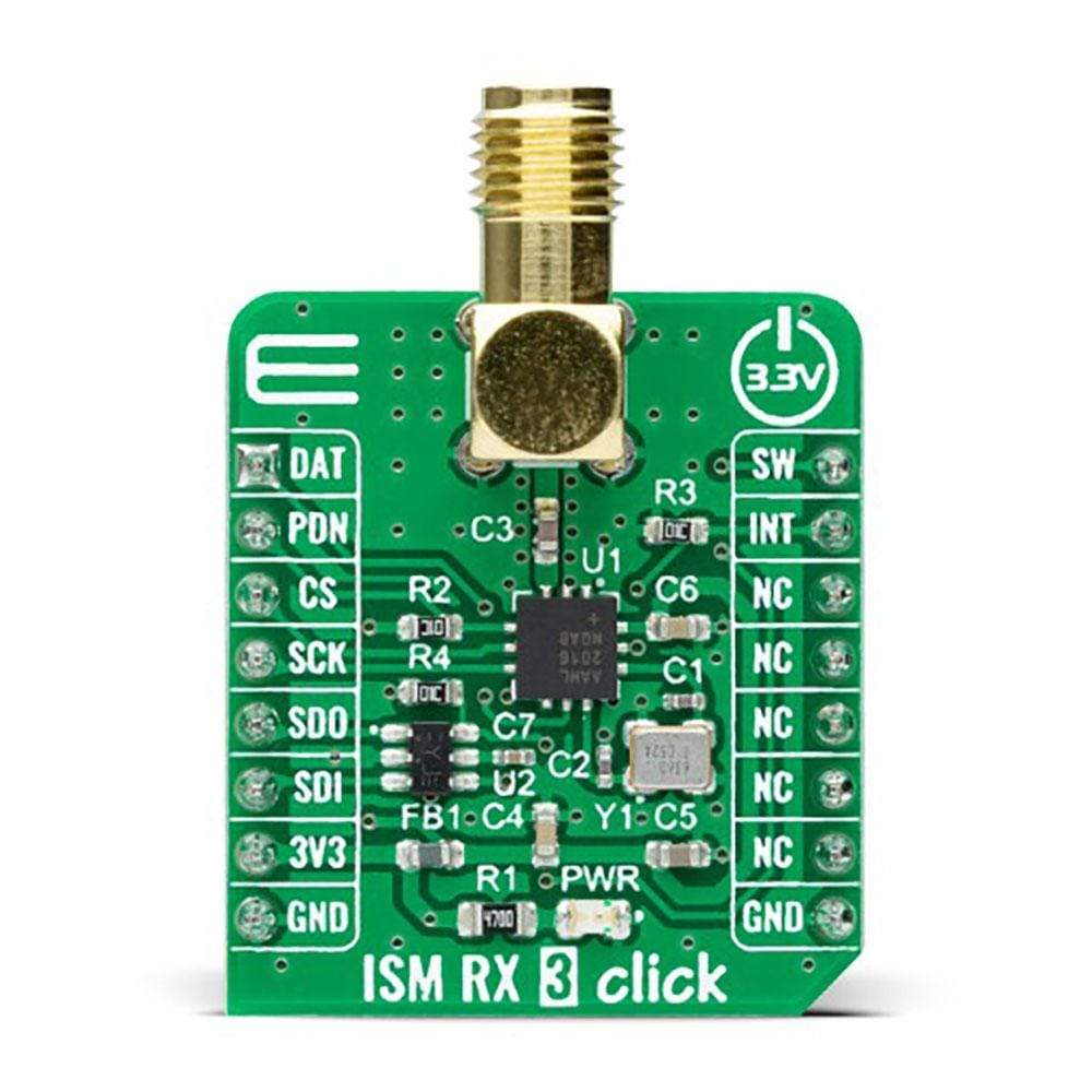
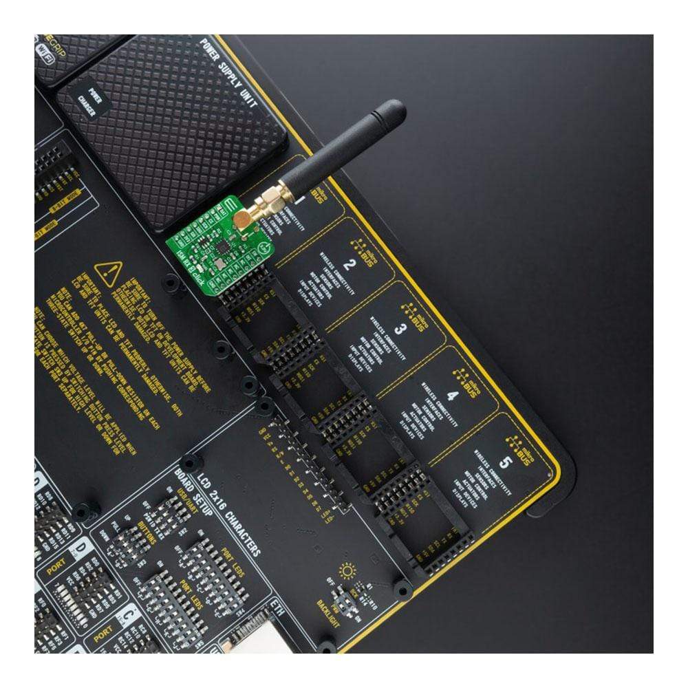
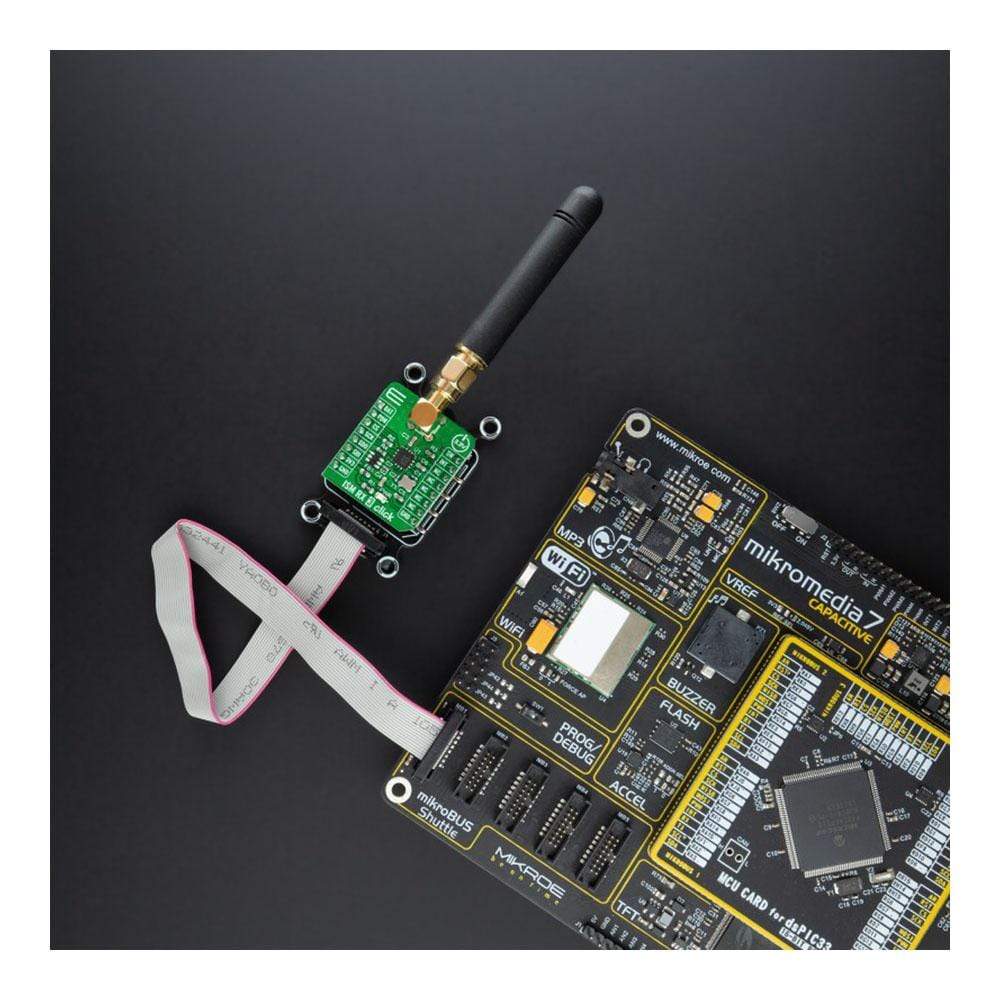
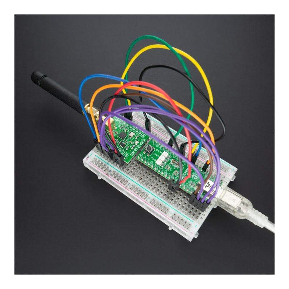
The ISM RX 3 Click Board™ is a compact add-on board that contains a Sub-GHz RF receiver. This board features the MAX41470, a high-performance, low-power receiver ideal for amplitude shift-keyed (ASK) and frequency shift-keyed (FSK) data from Maxim Integrated, now part of Analog Devices. It can be configured for three sub-1GHz bands using an onboard 16MHz crystal: 287MHz to 320MHz, 425MHz to 480MHz, and 860MHz to 960MHz, fully programmable through an SPI interface. The receiver has excellent RF sensitivity and long-range, allows input signals up to 0dBm of power at the RF input, and features a fully programmable, self-polling (duty cycling) mode with preamble detection and interrupt output to wake up an external MCU.
The ISM RX 3 Click Board™ is suitable for cost- and power-sensitive applications, such as home automation and security, building access control, remote keyless entry, garage or gate doors control, and similar applications.
Downloads
Der ISM RX 3 Click Board™ ist eine kompakte Zusatzplatine, die einen Sub-GHz-HF-Empfänger enthält. Diese Platine verfügt über den MAX41470, einen leistungsstarken, stromsparenden Empfänger, der sich ideal für Amplituden-Shift-Keyed (ASK) und Frequency-Shift-Keyed (FSK)-Daten von Maxim Integrated, jetzt Teil von Analog Devices, eignet. Er kann mit einem integrierten 16-MHz-Quarz für drei Sub-1-GHz-Bänder konfiguriert werden: 287 MHz bis 320 MHz, 425 MHz bis 480 MHz und 860 MHz bis 960 MHz, vollständig programmierbar über eine SPI-Schnittstelle. Der Empfänger verfügt über eine ausgezeichnete HF-Empfindlichkeit und große Reichweite, ermöglicht Eingangssignale mit bis zu 0 dBm Leistung am HF-Eingang und verfügt über einen vollständig programmierbaren Selbstabfragemodus (Duty Cycling) mit Präambelerkennung und Interrupt-Ausgang zum Aufwecken einer externen MCU.
Das ISM RX 3 Click Board™ eignet sich für kosten- und stromsensible Anwendungen wie Heimautomatisierung und -sicherheit, Gebäudezugangskontrolle, schlüssellose Fernzugangstechnik, Garagen- oder Torsteuerung und ähnliche Anwendungen.
| General Information | |
|---|---|
Part Number (SKU) |
MIKROE-4828
|
Manufacturer |
|
| Physical and Mechanical | |
Weight |
0.02 kg
|
| Other | |
EAN |
8606027383908
|
Frequently Asked Questions
Have a Question?
Be the first to ask a question about this.