


Mikroelektronika d.o.o.
Lüfter 8 Click-Platine
Lüfter 8 Click-Platine
SKU: MIKROE-4824
Verfügbarkeit für Abholungen konnte nicht geladen werden


Overview
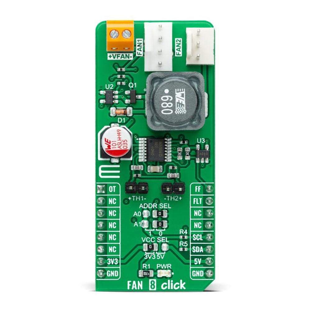
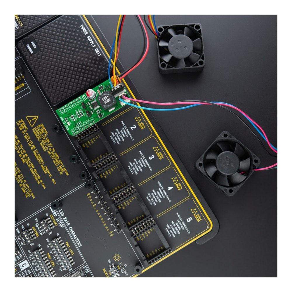
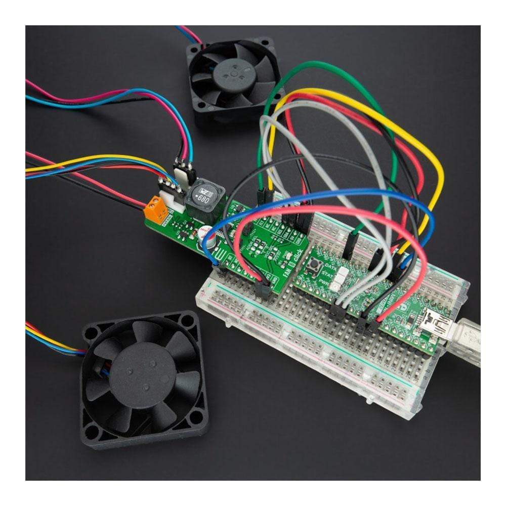
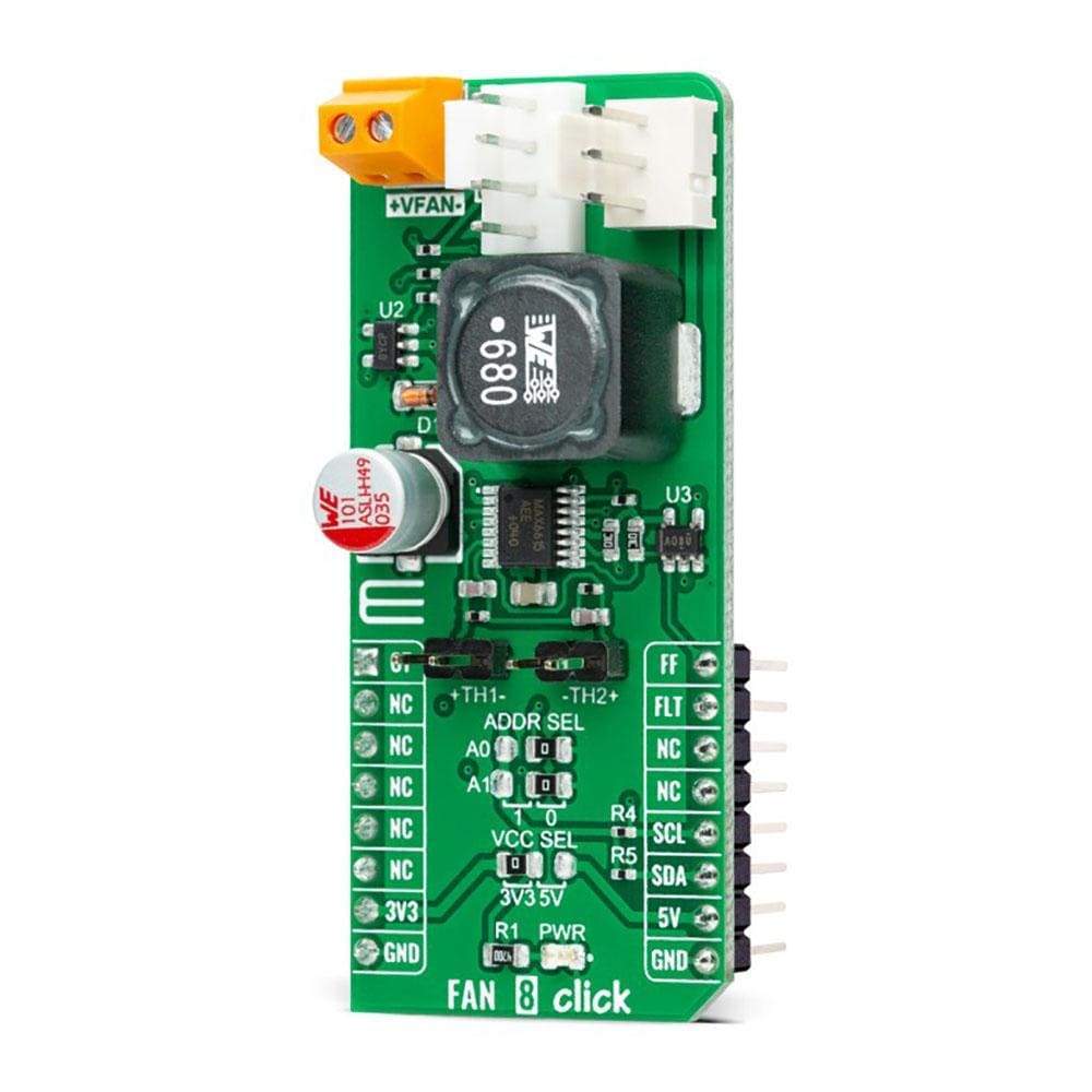
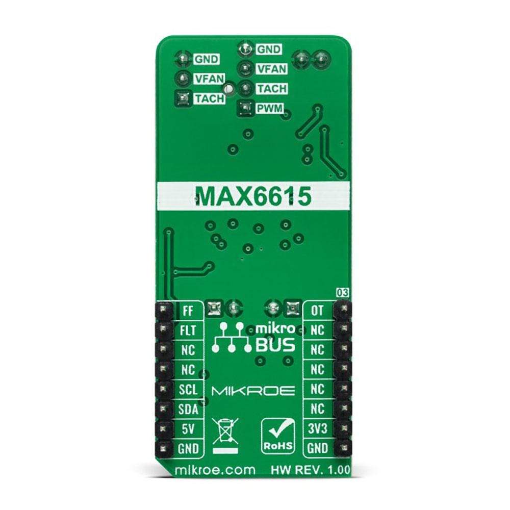
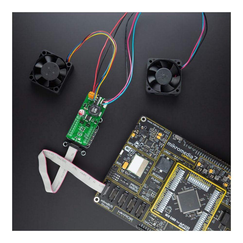
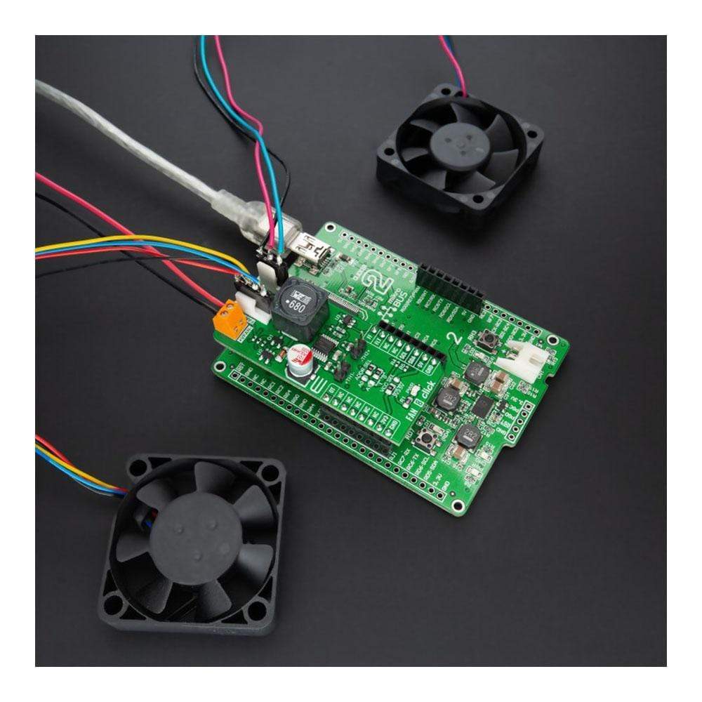
The Fan 8 Click Board™ is a compact add-on board that represents a compliant fan controller. This board features the MAX6615, a fan-speed controller, and a dual-channel temperature monitor with external thermistor inputs from Maxim Integrated, now part of Analog Devices. The MAX6615 controls the speed of two cooling fans based on the temperatures of external thermistors and the device's internal temperature, reporting temperature values in a digital form using the I2C serial interface. The temperature data controls a PWM output signal to adjust the speed of a cooling fan, minimizing noise when the system is running cool, but providing maximum cooling when power dissipation increases.
It also features an overtemperature alarm to generate interrupts, throttle, or shutdown signals. The combination of high accuracy and dual thermistor inputs makes this Click board a practical choice for networking equipment, servers, or other applications requiring cooling and temperature control.
Downloads
Der Fan 8 Click Board™ ist eine kompakte Zusatzplatine, die einen kompatiblen Lüfterregler darstellt. Diese Platine verfügt über den MAX6615, einen Lüfterdrehzahlregler, und einen Zweikanal-Temperaturmonitor mit externen Thermistoreingängen von Maxim Integrated, jetzt Teil von Analog Devices. Der MAX6615 steuert die Drehzahl von zwei Kühllüftern basierend auf den Temperaturen externer Thermistoren und der internen Temperatur des Geräts und meldet Temperaturwerte in digitaler Form über die serielle I2C-Schnittstelle. Die Temperaturdaten steuern ein PWM-Ausgangssignal, um die Drehzahl eines Kühllüfters anzupassen, wodurch die Geräuschentwicklung minimiert wird, wenn das System kühl läuft, aber maximale Kühlung gewährleistet wird, wenn die Verlustleistung zunimmt.
Es verfügt außerdem über einen Übertemperaturalarm zum Generieren von Interrupts, Drossel- oder Abschaltsignalen. Die Kombination aus hoher Genauigkeit und dualen Thermistoreingängen macht diese Click-Platine zu einer praktischen Wahl für Netzwerkgeräte, Server oder andere Anwendungen, die Kühlung und Temperaturregelung erfordern.
| General Information | |
|---|---|
Part Number (SKU) |
MIKROE-4824
|
Manufacturer |
|
| Physical and Mechanical | |
Weight |
0.02 kg
|
| Other | |
EAN |
8606027383915
|
Frequently Asked Questions
Have a Question?
Be the first to ask a question about this.