Ambient 10 Click-Platine
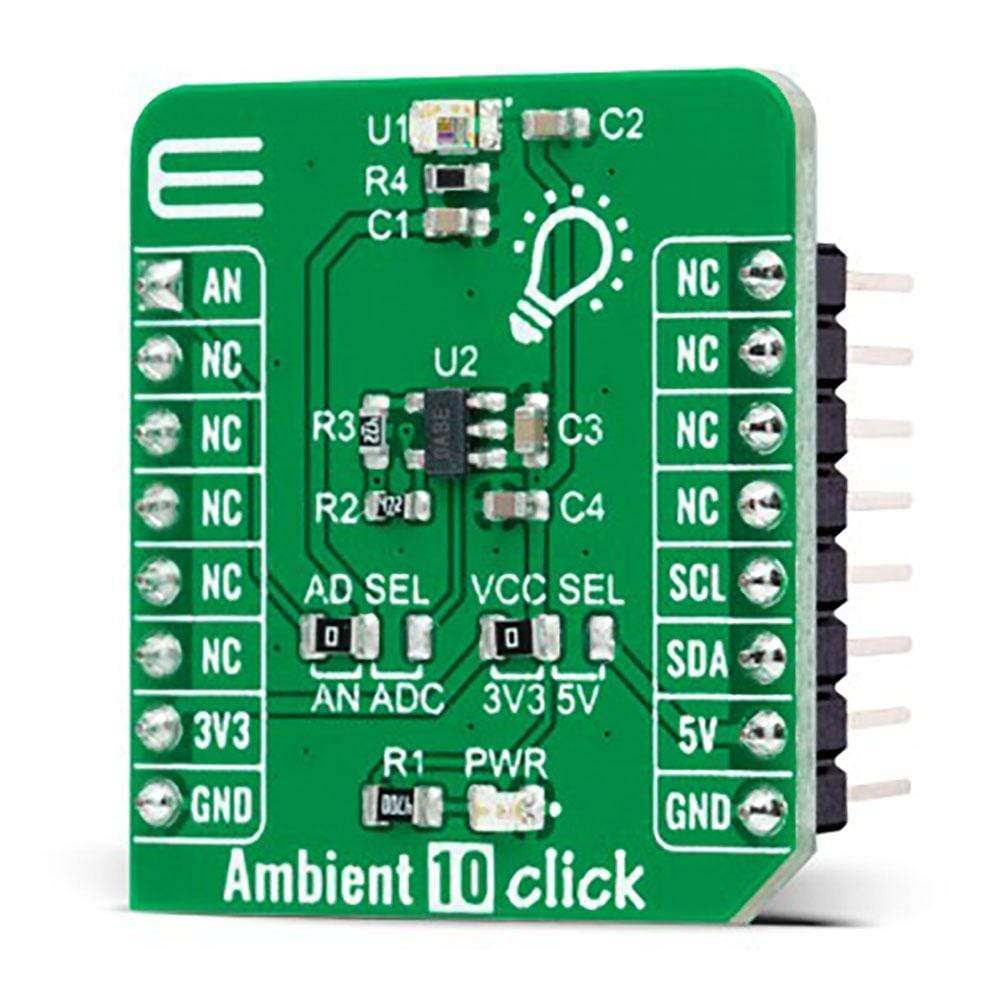
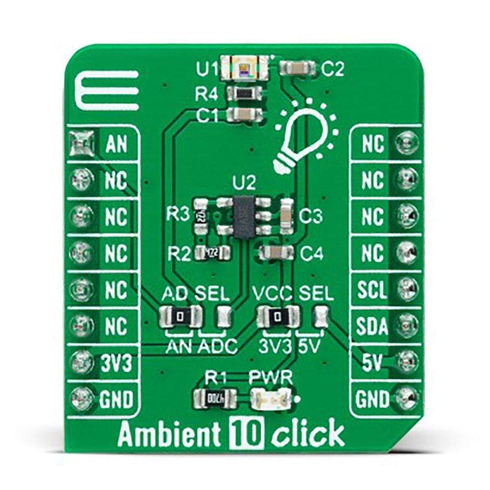
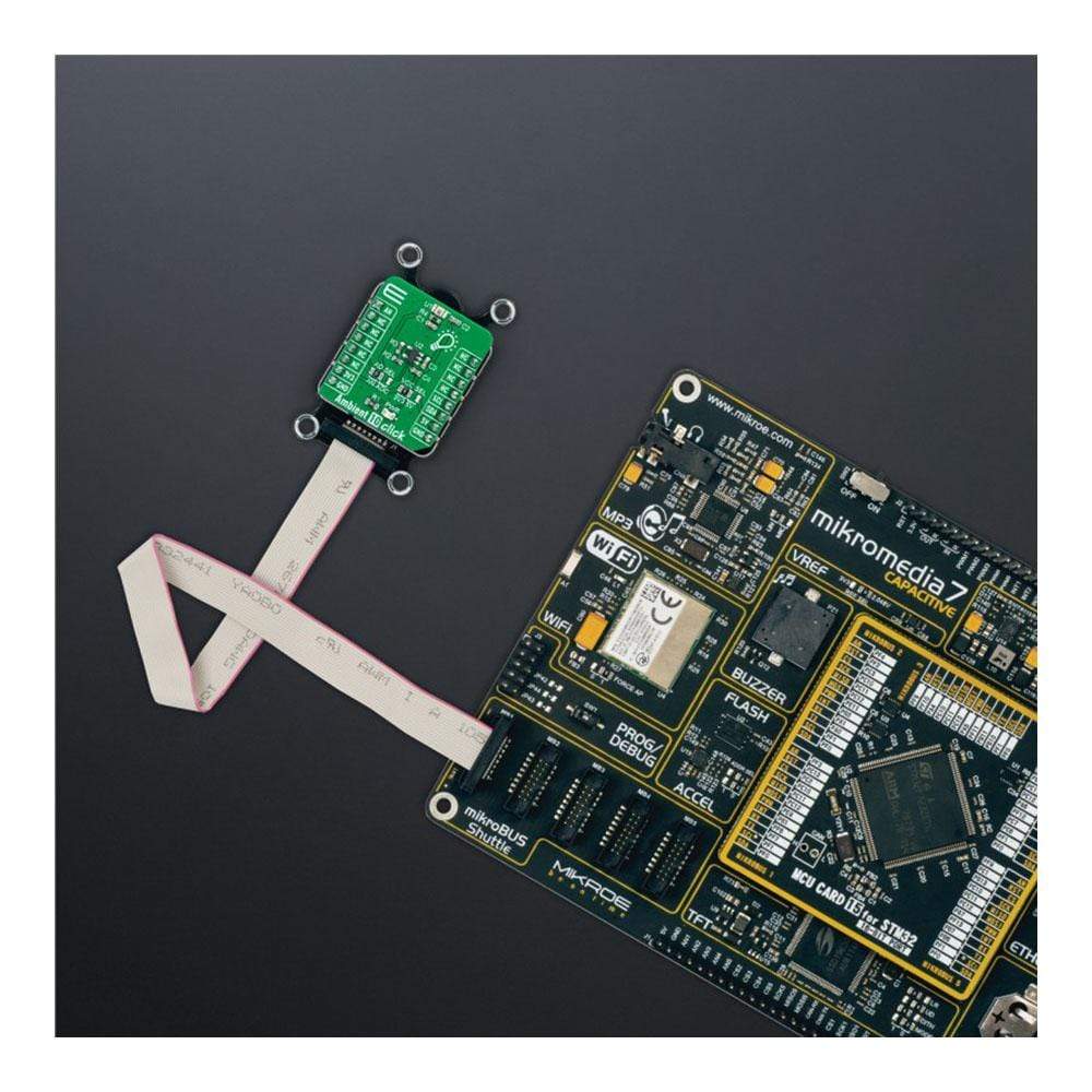
Der Ambient 10 Click Board™ ist eine kompakte Zusatzplatine, die zur Messung der Menge des vorhandenen Umgebungslichts verwendet wird. Diese Platine verfügt über den APDS-9006-020, einen Umgebungslicht-Fotosensor mit analogem Ausgang von Broadcom Limited. Er besteht aus einem spektral geeigneten Fotosensor, der eine ausgezeichnete Reaktionsfähigkeit bietet, die der Reaktion des menschlichen Auges nahe kommt. Darüber hinaus zeichnet er sich durch eine gute Ausgangslinearität über einen weiten Beleuchtungsbereich, geringe Empfindlichkeitsschwankungen über verschiedene Lichtquellen hinweg aus und bietet die Möglichkeit, das Ausgangssignal in analoger oder digitaler Form zu verarbeiten. Dieses Click Board™ eignet sich am besten zum Erfassen von Umgebungslichtdaten zur Anpassung der Helligkeit in Anwendungen, die Energieeinsparung und bessere Sichtbarkeit erfordern.
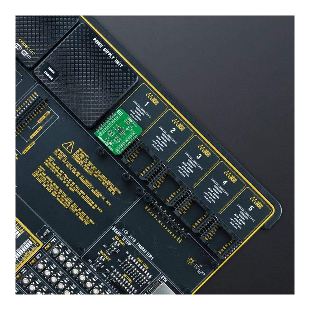
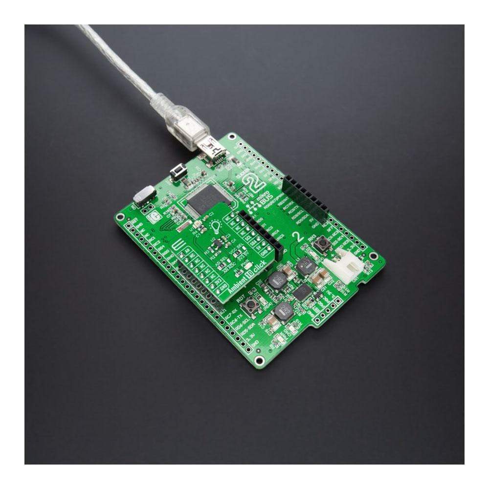
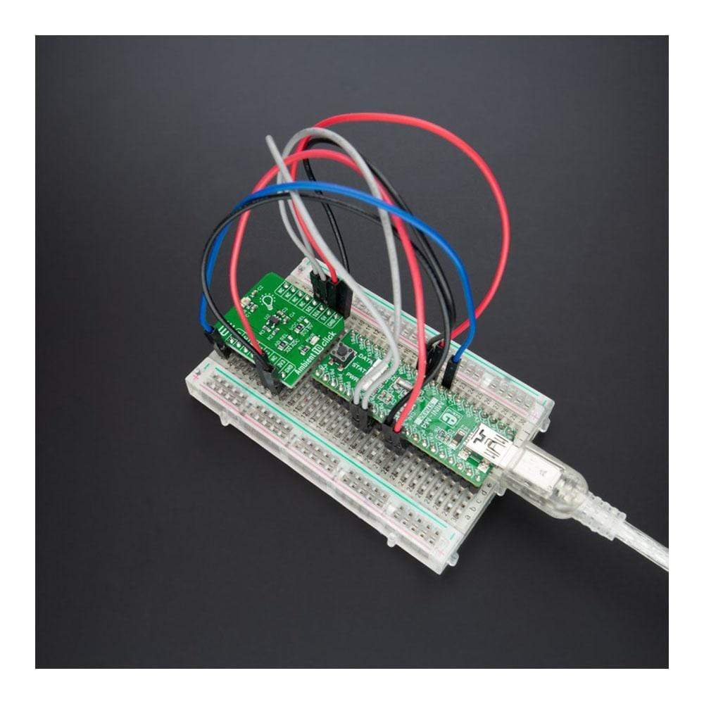
Das Ambient 10 Click Board™ wird von einer mikroSDK-kompatiblen Bibliothek unterstützt, die Funktionen enthält, die die Softwareentwicklung vereinfachen. Dieses Click Board™ wird als vollständig getestetes Produkt geliefert und ist bereit für den Einsatz auf einem System, das mit der mikroBUS™-Buchse ausgestattet ist.
How Does The Ambient 10 Click Board™ Work?
The Ambient 10 Click Board™ as its foundation uses the APDS-9006-020, analog-output ambient light photo sensor from Broadcom Limited. It consists of a photosensor whose spectral response is close to CIE standard photopic observer. Hence, it provides an excellent responsivity that is close to the response of human eyes. It has stable performance over a wide temperature and voltage range. It is characterized by good output linearity across a wide illumination range and low sensitivity variation across various light sources suitable to sense the amount of the present ambient light.
The analog output signal of the APDS-9006-020 can be converted to a digital value using MCP3221, a successive approximation A/D converter with a 12-bit resolution from Microchip, using a 2-wire I2C compatible interface, or can be sent directly to an analog pin of the mikroBUS™ socket labeled as AN. Selection can be performed by onboard SMD jumper labeled as A/D SEL to an appropriate position marked as AN and ADC.
The MCP3221 provides one single-ended input with low power consumption, a low maximum conversion current, and a Standby current of 250μA and 1μA, respectively. Data can be transferred at rates of up to 100kbit/s in the Standard and 400kbit/s in the Fast Mode. Also, maximum sample rates of 22.3kSPS with the MCP3221 are possible in a Continuous-Conversion Mode with a clock rate of 400kHz.
The Ambient 10 Click Board™ can operate with both 3.3V and 5V logic voltage levels selected via the VCC SEL jumper. This way, it is allowed for both 3.3V and 5V capable MCUs to use the communication lines properly. However, the Click board™ comes equipped with a library containing easy-to-use functions and an example code that can be used, as a reference, for further development.
Specifications
Type | Optical |
Applications | Can be used for obtaining ambient light data for adjusting brightness in applications that require power saving and better visibility |
On-board modules | APDS-9006-020 - analog-output ambient light photosensor from Broadcom Limited |
Key Features | Low power consumption, excellent responsivity which peaks in the human luminosity curve, close responsivity to the human eye, good output linearity across wide illumination range, low sensitivity variation across various light sources, stable performance over temperature and voltage, and more |
Interface | Analog,I2C |
Compatibility | mikroBUS |
Click board size | S (28.6 x 25.4 mm) |
Input Voltage | 3.3V or 5V |
Pinout diagram
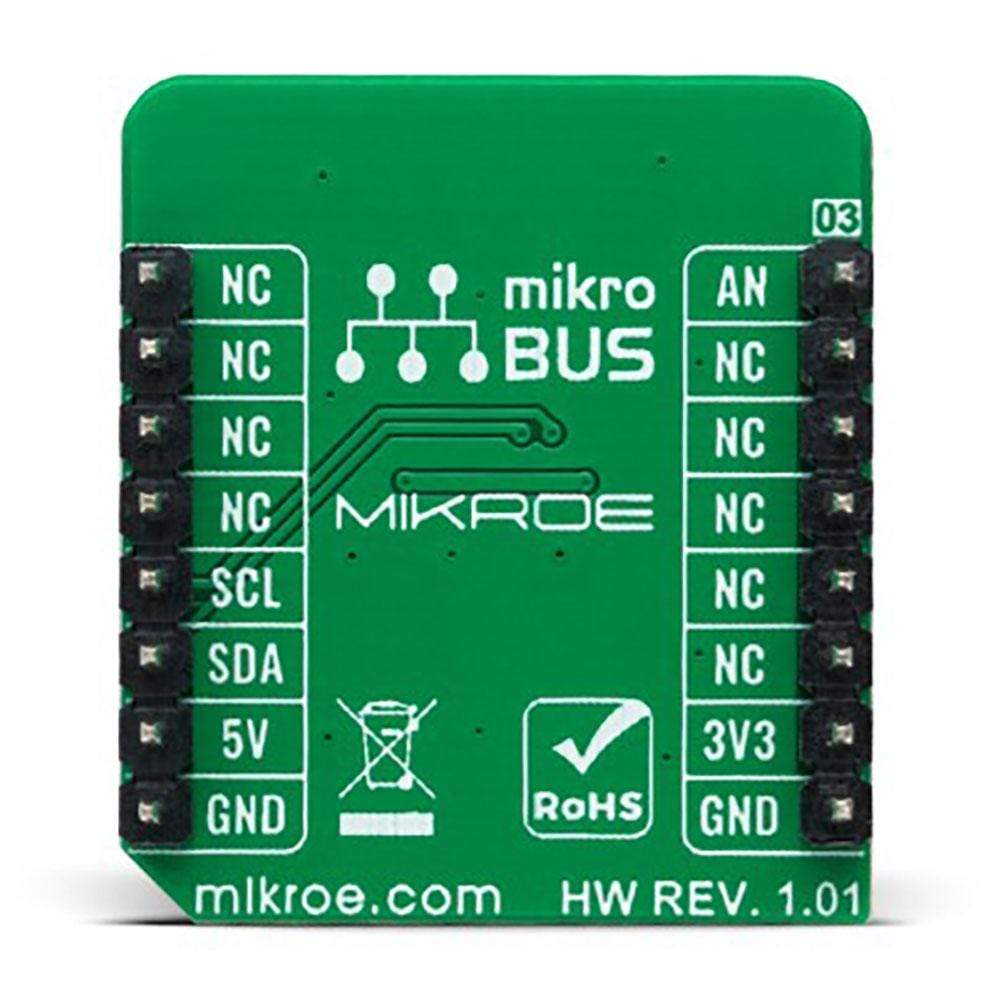
This table shows how the pinout of the Ambient 10 Click Board™ corresponds to the pinout on the mikroBUS™ socket (the latter shown in the two middle columns).
Notes | Pin | Pin | Notes | ||||
---|---|---|---|---|---|---|---|
Analog Signal | AN | 1 | AN | PWM | 16 | NC | |
NC | 2 | RST | INT | 15 | NC | ||
NC | 3 | CS | RX | 14 | NC | ||
NC | 4 | SCK | TX | 13 | NC | ||
NC | 5 | MISO | SCL | 12 | SCL | I2C Clock | |
NC | 6 | MOSI | SDA | 11 | SDA | I2C Data | |
Power Supply | 3.3V | 7 | 3.3V | 5V | 10 | 5V | Power Supply |
Ground | GND | 8 | GND | GND | 9 | GND | Ground |
Onboard settings and indicators
Label | Name | Default | Description |
---|---|---|---|
LD1 | PWR | - | Power LED Indicator |
JP1 | VCC SEL | Left | Logic Level Voltage Selection 3V3/5V: Left position 3V3, Right position 5V |
JP2 | AD SEL | Left | Output Voltage A/D Selection AN/ADC: Left position AN, Right position ADC |
Ambient 10 Click electrical specifications
Description | Min | Typ | Max | Unit |
---|---|---|---|---|
Supply Voltage | 3.3 | - | 5 | V |
Peak Wavelength | - | 500 | - | nm |
Operating Temperature Range | -40 | +25 | +85 | °C |
Software Support
We provide a library for the Ambient 10 Click Board™ as well as a demo application (example), developed using MikroElektronika compilers. The demo can run on all the main MikroElektronika development boards.
Package can be downloaded/installed directly from NECTO Studio Package Manager(recommended way), downloaded from our LibStock™ or found on Mikroe github account.
Library Description
This library contains API for Ambient 10 Click driver.
Key Functions
ambient10_cfg_setup
- Config Object Initialization function.ambient10_init
- Initialization function.
Example Description
This example demonstrates the use of Ambient 10 click board.
The demo application is composed of two sections :
void application_task ( void ) { float voltage = 0; if ( AMBIENT10_OK == ambient10_read_adc_voltage ( &ambient10, &voltage ) ) { log_printf( &logger, " Illuminance : %u Luxrnn", ambient10_voltage_to_lux( &ambient10, voltage ) ); } Delay_ms( 1000 ); }
The full application code, and ready to use projects can be installed directly from NECTO Studio Package Manager(recommended way), downloaded from our LibStock™ or found on Mikroe github account.
Other Mikroe Libraries used in the example:
- MikroSDK.Board
- MikroSDK.Log
- Click.Ambient10
Additional Notes and Information
Depending on the development board you are using, you may need USB UART click, USB UART 2 click or RS232 click to connect to your PC, for development systems with no UART to USB interface available on the board. The terminal available in all MikroElektronika compilers, or any other terminal application of your choice, can be used to read the message.
mikroSDK
This Click board™ is supported with mikroSDK - MikroElektronika Software Development Kit. To ensure proper operation of mikroSDK compliant Click board™ demo applications, mikroSDK should be downloaded from the LibStock and installed for the compiler you are using.
Ambient 10 Click-Platine
Frequently Asked Questions
Have a Question?
Be the first to ask a question about this.