


Mikroelektronika d.o.o.
ISM Click-Platine
ISM Click-Platine
SKU: MIKROE-4625
Verfügbarkeit für Abholungen konnte nicht geladen werden


Overview
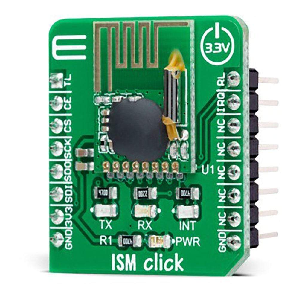
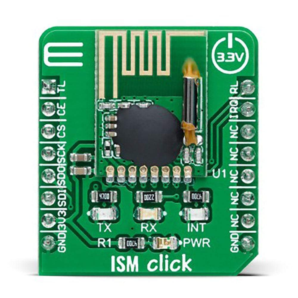
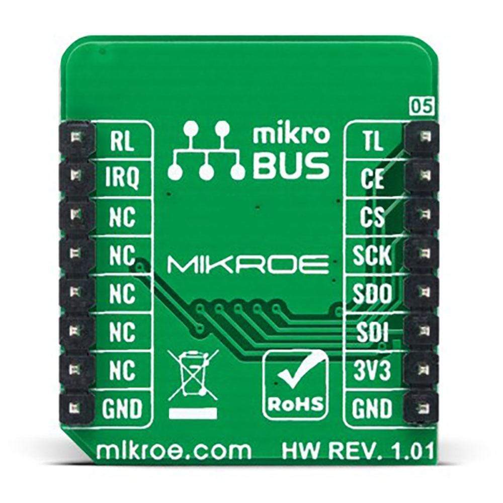
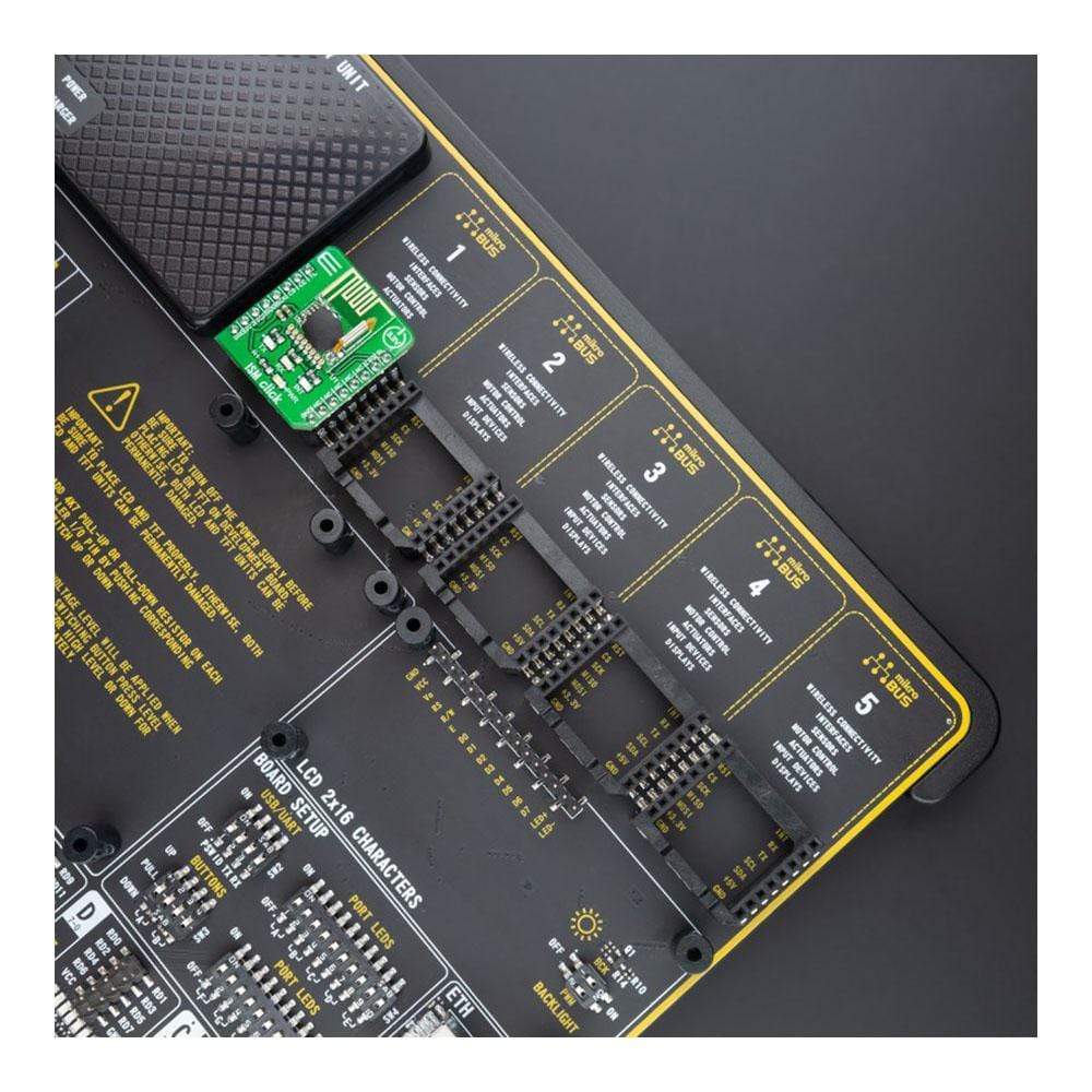
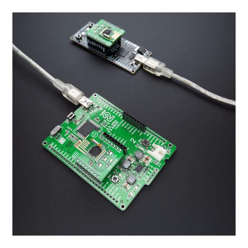
The ISM Click Board™ is a compact add-on board that contains a complete wireless RF digital data transceiver. This board features the RFM75, a low-power, high-performance 2.4GHz GFSK transceiver from RF Solutions. The RFM75 transceiver is configurable through SPI serial interface and operates with only 3.3V in the worldwide ISM frequency band from 2400MHz up to 2527MHz. The embedded packet processing engines enable their entire operation with a simple MCU as a radio system. Burst mode transmission and up to 2Mbps air data rate make it suitable for ultra-low power consumption applications.
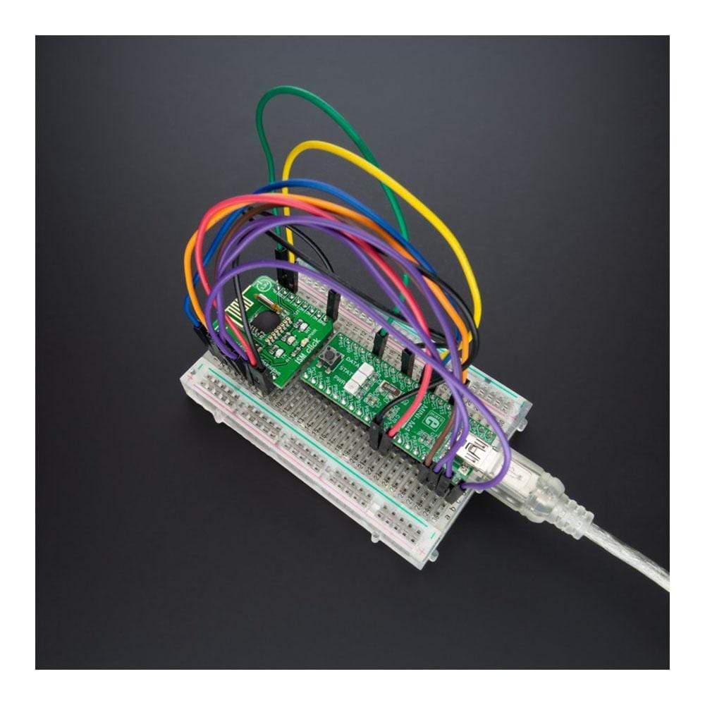
This ISM Click Board™ is ideal for home appliances, remote control applications, consumer electronics, and many more.
Downloads
Der ISM Click Board™ ist eine kompakte Zusatzplatine, die einen kompletten drahtlosen digitalen HF-Datentransceiver enthält. Diese Platine verfügt über den RFM75, einen stromsparenden, leistungsstarken 2,4-GHz-GFSK-Transceiver von RF Solutions. Der RFM75-Transceiver ist über die serielle SPI-Schnittstelle konfigurierbar und arbeitet mit nur 3,3 V im weltweiten ISM-Frequenzband von 2400 MHz bis 2527 MHz. Die eingebetteten Paketverarbeitungs-Engines ermöglichen ihren gesamten Betrieb mit einer einfachen MCU als Funksystem. Durch die Burst-Modus-Übertragung und eine Luftdatenrate von bis zu 2 Mbit/s ist sie für Anwendungen mit extrem geringem Stromverbrauch geeignet.
Dieses ISM Click Board™ ist ideal für Haushaltsgeräte, Fernbedienungsanwendungen, Unterhaltungselektronik und vieles mehr.
| General Information | |
|---|---|
Part Number (SKU) |
MIKROE-4625
|
Manufacturer |
|
| Physical and Mechanical | |
Weight |
0.02 kg
|
| Other | |
EAN |
8606027382765
|
Frequently Asked Questions
Have a Question?
Be the first to ask a question about this.