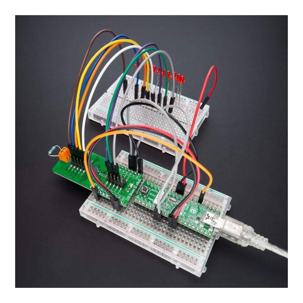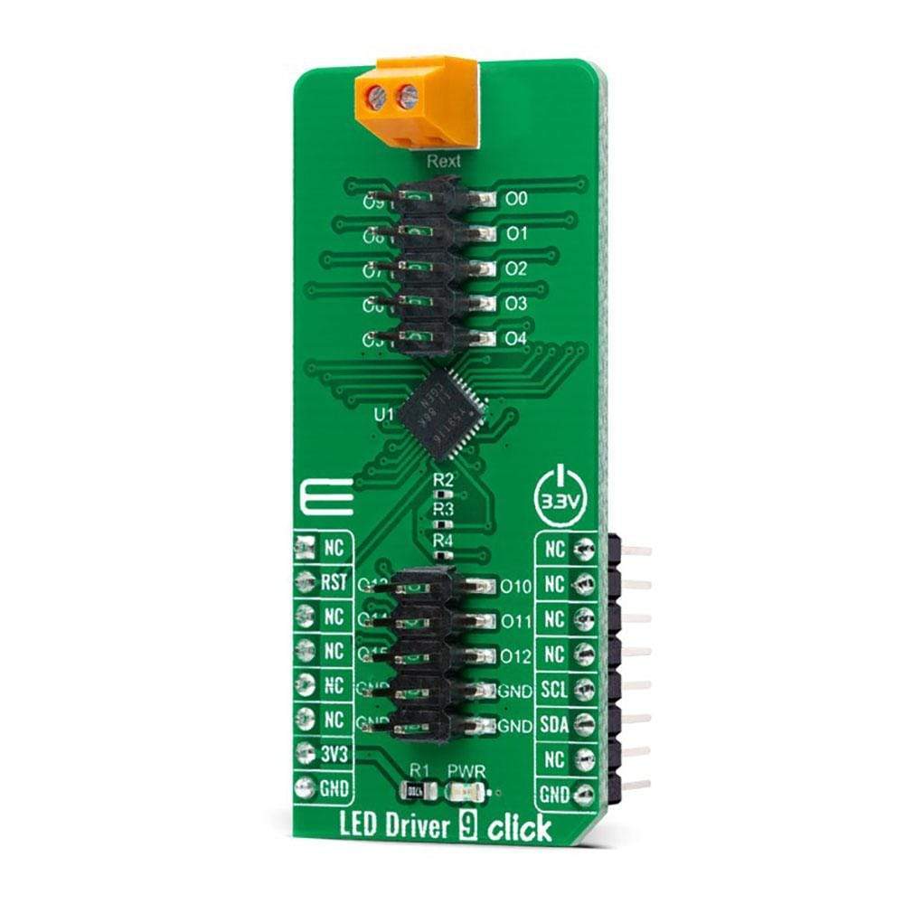
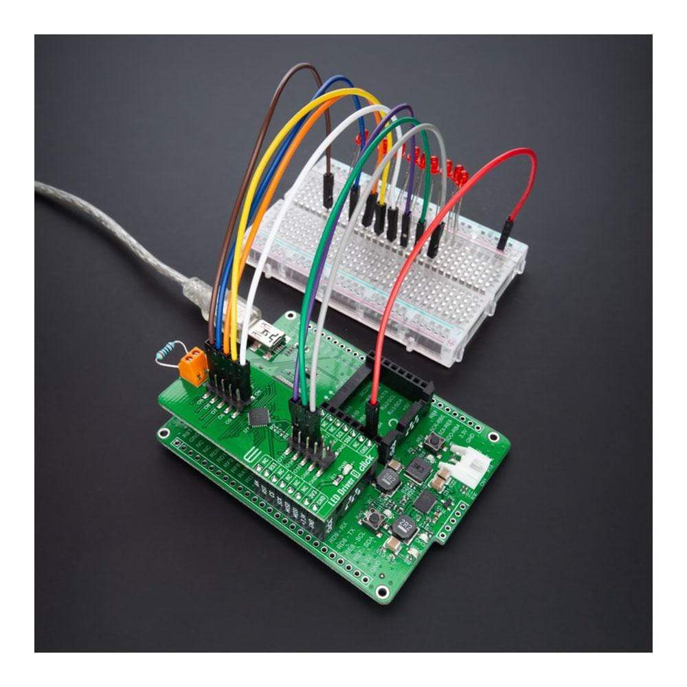
LED-Treiber 9 Click-Platine
Key Features
- 16 programmierbare LED-Treiber, Ausgangsstrom über einen externen Widerstand eingestellt, unterstützt Hot Insertion, programmierbares Gruppendimmen und -blinken und vieles mehr.
- Basierend auf dem TLC59116 - I2C-Bus-gesteuerter 16-Kanal-LED-Treiber, optimiert für die Farbmischung Rot/Grün/Blau/Bernstein (RGBA) und Hintergrundbeleuchtungsanwendung von Texas Instruments
- Kann für RGBA-Farbmischung und Hintergrundbeleuchtungsanwendungen für Unterhaltungsprodukte, LED-Statussignalisierung, Heimautomatisierungsprojekte, Industrieanlagen und vieles mehr verwendet werden.
- mikroBUS: I2C-Schnittstelle
Overview
Der LED Driver 9 Click Board™ ist eine kompakte Zusatzplatine, die die Steuerung mehrerer LEDs vereinfacht. Diese Platine verfügt über den TLC59116, einen I2C-busgesteuerten 16-Kanal-LED-Treiber, der für die Farbmischung Rot/Grün/Blau/Gelb (RGBA) und Hintergrundbeleuchtungsanwendungen von Texas Instruments optimiert ist. Jeder 16-Kanal-LED-Ausgang hat eine 8-Bit-Auflösung (256 Schritte), eine Festfrequenz, einen individuellen PWM-Controller, der mit 97 kHz arbeitet, mit einem von 0 % bis 99,6 % einstellbaren Arbeitszyklus. Der PWM-Controller ermöglicht die Einstellung jeder LED auf einen bestimmten Helligkeitswert und dimmt oder blinkt alle LEDs mit demselben Wert. Dieses Click Board™ eignet sich für die RGBA-Farbmischung und Hintergrundbeleuchtungsanwendungen für Unterhaltungsprodukte, LED-Statussignalisierung, Heimautomatisierungsprojekte, Industrieanlagen und vieles mehr.
Der LED-Treiber 9 Click Board™ wird durch eine mikroSDK-kompatible Bibliothek unterstützt, die Funktionen enthält, die die Softwareentwicklung vereinfachen. Dieses Click Board™ wird als vollständig getestetes Produkt geliefert und ist bereit für den Einsatz auf einem System, das mit der mikroBUS™-Buchse ausgestattet ist.
How Does The LED Driver 9 Click Board™ Work?
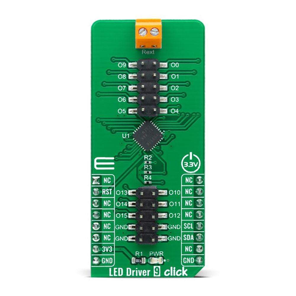
The LED Driver 9 Click Board™ as its foundation uses the TLC59116, an I2C bus controlled 16-channel LED driver optimized for red/green/blue/amber (RGBA) colour mixing and backlight application from Texas Instruments. It operates within a VCC supply voltage range where its outputs are 17V tolerant. Each LED output, 16 LED drivers presented on two 2x5 male headers, with a maximum output current of 120mA per channel, is programmable at OFF and ON state, has programmable individual LED brightness with group dimming and blinking.
Each LED output has its individual PWM controller, which allows each LED to be set at a specific brightness value. An additional 8-bit resolution (256 steps) group PWM controller has a fixed frequency of 190Hz and an adjustable frequency between 24Hz to once every 10.73 seconds, with an adjustable duty cycle from 0% to 99.6%.
The LED Driver 9 Click Board™ communicates with MCU using standard I2C 2-Wire interface, with a clock frequency up to 100kHz in the Standard, 400kHz in the Fast, and 1MHz in the Fast Mode Plus. The Software Reset feature allows the MCU to perform a reset of the TLC59116 through the I2C bus, identical to the Power-On Reset (POR) that initializes the registers to their default state, causing the outputs to be set high, which means that the LEDs are OFF. This allows an easy and quick way to reconfigure all device registers to the same condition. Also, this Click board™ has a Reset pin routed to the RST pin on the mikroBUS™ socket, which holds registers in their default states until the RST pin is set to a logic high state.
At the top of this Click board™, there is also a terminal labelled Rext used to connect an external resistor to set the LED current. The TLC59116 scales up the reference current set by the external resistor to sink the output current at each output port.
The LED Driver 9 Click Board™ can be operated only with a 3.3V logic voltage level. The board must perform appropriate logic voltage level conversion before use with MCUs with different logic levels. However, the Click board™ comes equipped with a library containing functions and an example code that can be used, as a reference, for further development.
SPECIFICATIONS
Type | LED Drivers |
Applications | Can be used for RGBA colour mixing and backlight application for amusement products, LED status signalization, home automation projects, industrial equipment, and many more. |
On-board modules | TLC59116 - I2C bus controlled 16-channel LED driver optimized for red/green/blue/amber (RGBA) colour mixing and backlight application from Texas Instruments |
Key Features | 16 LED programmable drivers, output current adjusted through an external resistor, supports hot insertion, programmable group dimming and blinking, and many more. |
Interface | I2C |
Compatibility | mikroBUS |
Click board size | L (57.15 x 25.4 mm) |
Input Voltage | 3.3V |
PINOUT DIAGRAM
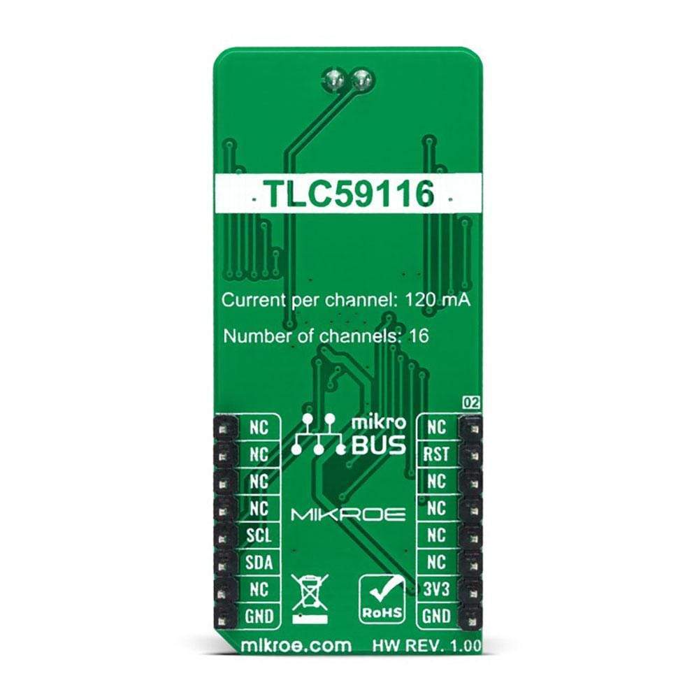
This table shows how the pinout on the LED Driver 9 Click Board™ corresponds to the pinout on the mikroBUS™ socket (the latter shown in the two middle columns).
Notes | Pin | Pin | Notes | ||||
---|---|---|---|---|---|---|---|
NC | 1 | AN | PWM | 16 | NC | ||
Reset | RST | 2 | RST | INT | 15 | NC | |
NC | 3 | CS | RX | 14 | NC | ||
NC | 4 | SCK | TX | 13 | NC | ||
NC | 5 | MISO | SCL | 12 | SCL | I2C Clock | |
NC | 6 | MOSI | SDA | 11 | SDA | I2C Data | |
Power Supply | 3.3V | 7 | 3.3V | 5V | 10 | NC | |
Ground | GND | 8 | GND | GND | 9 | GND | Ground |
ONBOARD SETTINGS AND INDICATORS
Label | Name | Default | Description |
---|---|---|---|
LD1 | PWR | - | Power LED Indicator |
J1-J2 | HM2x5 | Populated | LED Driver Channels |
LED DRIVER CLICK ELECTRICAL SPECIFICATIONS
Description | Min | Typ | Max | Unit |
---|---|---|---|---|
Supply Voltage | - | 3.3 | - | V |
Maximum Output Current | - | - | 120 | mA |
Maximum Output Voltage | - | - | 17 | V |
Operating Temperature Range | -40 | +25 | +85 | °C |
Software Support
We provide a library for the LED Driver 9 Click Board™ as well as a demo application (example), developed using MikroElektronika compilers. The demo can run on all the main MikroElektronika development boards.
The package can be downloaded/installed directly from NECTO Studio Package Manager(recommended way), downloaded from our LibStock™ or found on the mikroE Github account.
Library Description
This library contains API for the LED Driver 9 Click Board™ driver.
Key Functions
leddriver9_cfg_setup
- Config Object Initialization function.leddriver9_init
- Initialization function.leddriver9_default_cfg
- Click the Default Configuration function.
Example Description
The application is composed of three sections :
void application_task ( void ) { float duty_cnt = min_duty; while ( duty_cnt <= max_duty ) { leddriver9_set_pwm( &leddriver9, LEDDRIVER9_CHANNEL0, duty_cnt ); leddriver9_set_pwm( &leddriver9, LEDDRIVER9_CHANNEL1, duty_cnt ); leddriver9_set_pwm( &leddriver9, LEDDRIVER9_CHANNEL2, duty_cnt ); leddriver9_set_pwm( &leddriver9, LEDDRIVER9_CHANNEL3, duty_cnt ); leddriver9_set_pwm( &leddriver9, LEDDRIVER9_CHANNEL4, duty_cnt ); leddriver9_set_pwm( &leddriver9, LEDDRIVER9_CHANNEL5, duty_cnt ); leddriver9_set_pwm( &leddriver9, LEDDRIVER9_CHANNEL6, duty_cnt ); leddriver9_set_pwm( &leddriver9, LEDDRIVER9_CHANNEL7, duty_cnt ); leddriver9_set_pwm( &leddriver9, LEDDRIVER9_CHANNEL8, duty_cnt ); leddriver9_set_pwm( &leddriver9, LEDDRIVER9_CHANNEL9, duty_cnt ); leddriver9_set_pwm( &leddriver9, LEDDRIVER9_CHANNEL10, duty_cnt ); leddriver9_set_pwm( &leddriver9, LEDDRIVER9_CHANNEL11, duty_cnt ); leddriver9_set_pwm( &leddriver9, LEDDRIVER9_CHANNEL12, duty_cnt ); leddriver9_set_pwm( &leddriver9, LEDDRIVER9_CHANNEL13, duty_cnt ); leddriver9_set_pwm( &leddriver9, LEDDRIVER9_CHANNEL14, duty_cnt ); leddriver9_set_pwm( &leddriver9, LEDDRIVER9_CHANNEL15, duty_cnt ); duty_cnt += duty_gradient; Delay_ms( breathing_speed ); } while ( duty_cnt > min_duty ) { leddriver9_set_pwm( &leddriver9, LEDDRIVER9_CHANNEL0, duty_cnt ); leddriver9_set_pwm( &leddriver9, LEDDRIVER9_CHANNEL1, duty_cnt ); leddriver9_set_pwm( &leddriver9, LEDDRIVER9_CHANNEL2, duty_cnt ); leddriver9_set_pwm( &leddriver9, LEDDRIVER9_CHANNEL3, duty_cnt ); leddriver9_set_pwm( &leddriver9, LEDDRIVER9_CHANNEL4, duty_cnt ); leddriver9_set_pwm( &leddriver9, LEDDRIVER9_CHANNEL5, duty_cnt ); leddriver9_set_pwm( &leddriver9, LEDDRIVER9_CHANNEL6, duty_cnt ); leddriver9_set_pwm( &leddriver9, LEDDRIVER9_CHANNEL7, duty_cnt ); leddriver9_set_pwm( &leddriver9, LEDDRIVER9_CHANNEL8, duty_cnt ); leddriver9_set_pwm( &leddriver9, LEDDRIVER9_CHANNEL9, duty_cnt ); leddriver9_set_pwm( &leddriver9, LEDDRIVER9_CHANNEL10, duty_cnt ); leddriver9_set_pwm( &leddriver9, LEDDRIVER9_CHANNEL11, duty_cnt ); leddriver9_set_pwm( &leddriver9, LEDDRIVER9_CHANNEL12, duty_cnt ); leddriver9_set_pwm( &leddriver9, LEDDRIVER9_CHANNEL13, duty_cnt ); leddriver9_set_pwm( &leddriver9, LEDDRIVER9_CHANNEL14, duty_cnt ); leddriver9_set_pwm( &leddriver9, LEDDRIVER9_CHANNEL15, duty_cnt ); duty_cnt -= duty_gradient; Delay_ms( breathing_speed ); } }
The full application code, and ready to use projects can be installed directly from NECTO Studio Package Manager(recommended way), downloaded from our LibStock™ or found on the mikroE Github account.
Other mikroE Libraries used in the example:
- MikroSDK.Board
- MikroSDK.Log
- Click.LEDDriver9
Additional Notes and Information
Depending on the development board you are using, you may need a USB UART click, USB UART 2 click or RS232 click to connect to your PC, for development systems with no UART to USB interface available on the board. The terminal available in all MikroElektronika compilers, or any other terminal application of your choice, can be used to read the message.
MIKROSDK
The LED Driver 9 Click Board™is supported with mikroSDK - MikroElektronika Software Development Kit. To ensure proper operation of mikroSDK compliant Click board™ demo applications, mikroSDK should be downloaded from the LibStock and installed for the compiler you are using.
Frequently Asked Questions
Have a Question?
Be the first to ask a question about this.