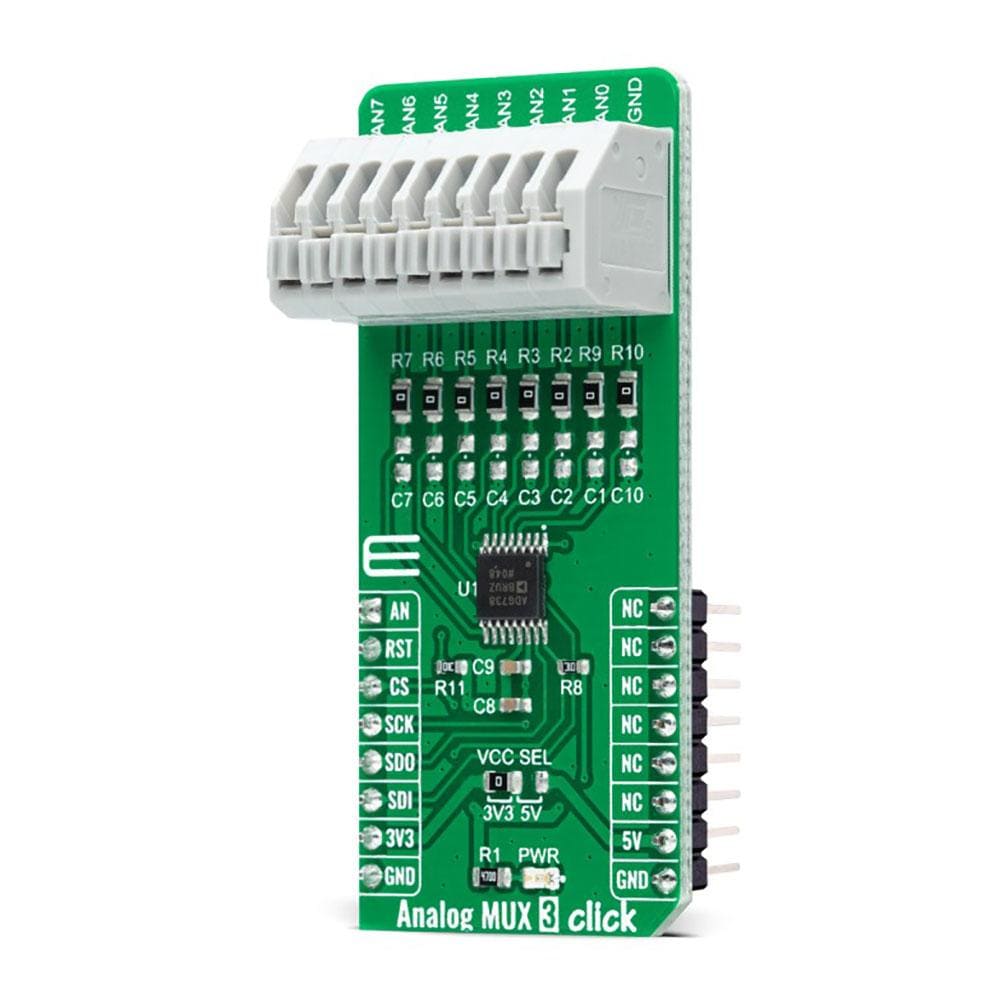
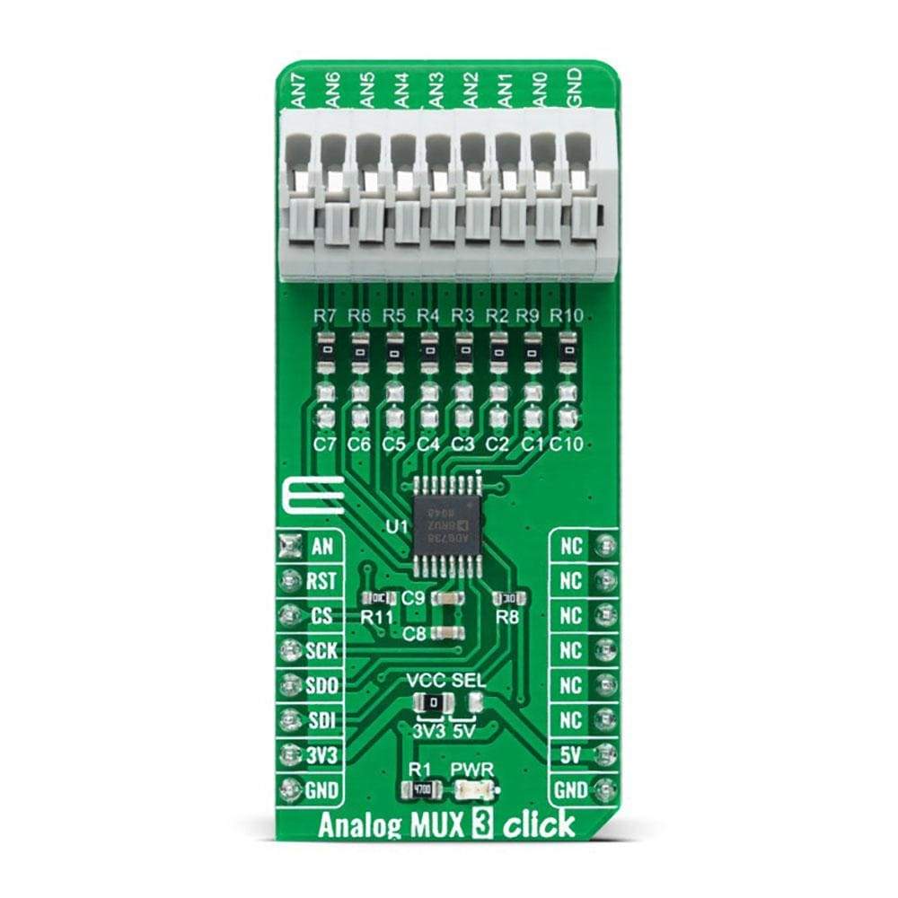
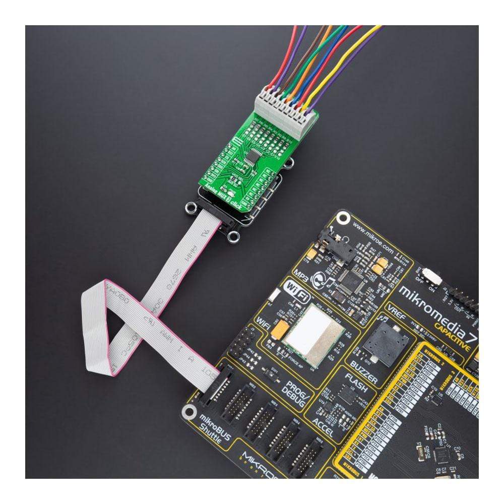
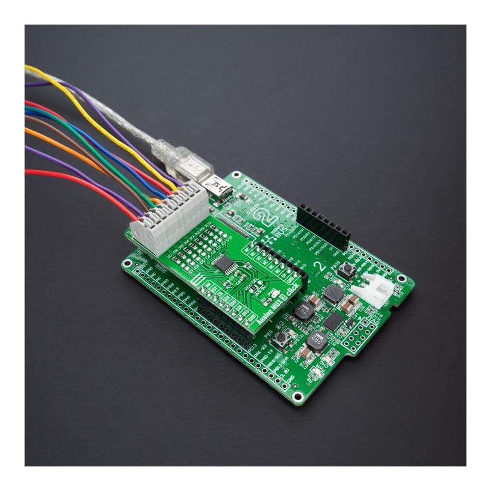
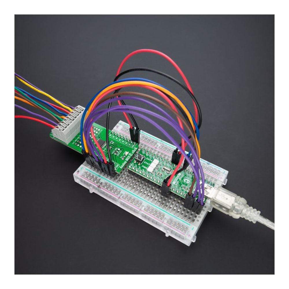
Analoge MUX 3 Click-Platine
Key Features
- 8-zu-1-Matrixschalter, niedriger Einschaltwiderstand, „Break-Before-Make“-Schaltfunktion, seriell gesteuert und mehr
- Basierend auf dem ADG738 - CMOS 8-Kanal-Analog-Matrixschalter mit seriell gesteuerter 3-Draht-SPI-Schnittstelle von Analog Devices
- Kann für eine breite Palette von Anwendungen verwendet werden, von Industrie- und Instrumentierungssystemen bis hin zu medizinischen, Verbraucher-, Kommunikations- und Automobilsystemen.
- mikroBUS: SPI und analoge Schnittstellen
Overview
Der Analog MUX 3 Click Board™ ist eine kompakte Zusatzplatine, die einen der acht Eingänge auf einen Ausgang umschaltet. Diese Platine verfügt über den ADG738, einen CMOS-Analogmatrixschalter mit einer seriell gesteuerten SPI-Schnittstelle von Analog Devices. Im aktiven Zustand leitet der ADG738 in beide Richtungen gleich gut und ist daher für Multiplexing- und Demultiplexing-Anwendungen geeignet. Er kann auch als eine Art Schalterarray konfiguriert werden, bei dem jeder, alle oder keiner der acht Schalter jederzeit geschlossen sein kann. Alle Kanäle weisen eine „Break-Before-Make“-Schaltfunktion auf, die kurzzeitige Kurzschlüsse beim Umschalten der Kanäle verhindert. Dieses Click Board™ ist für eine Vielzahl von Anwendungen geeignet, von Industrie und Instrumentierung bis hin zu medizinischen, Verbraucher-, Kommunikations- und Automobilsystemen.
Der Analog MUX 3 Click wird durch eine mikroSDK-kompatible Bibliothek unterstützt, die Funktionen enthält, die die Softwareentwicklung vereinfachen. Dieses Click Board™ wird als vollständig getestetes Produkt geliefert und ist bereit für den Einsatz auf einem System, das mit der mikroBUS™-Buchse ausgestattet ist.
How Does The Analog MUX 3 Click Board™ Work?
The Analog MUX 3 Click Board™ uses the ADG738, a CMOS 8-channel analogue matrix switch with a serially-controlled SPI interface from Analog Devices. The ADG738 can operate equally well as either multiplexer, demultiplexer, or switch array, providing more flexibility. It also features a low on-resistance closely matched between switches and very flat over the entire signal range. During the Power-Up of the ADG738, all switching channels will be in the OFF condition, and the internal shift register will contain all zeros and remains so until a valid write takes place. All channels exhibit 'break-before-make switching action preventing momentary shorting when switching channels.
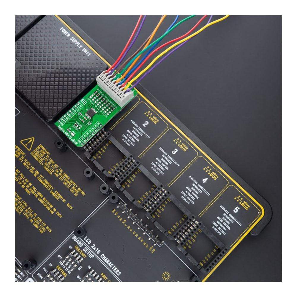
Each bit of the 8-bit serial word corresponds to one switch of the device. Internal switching channels are independently controlled by an individual bit, providing an option of having any, all, or none of the switches activated. All of the input channels of the multiplexer can be easily connected to a nine pole spring action block terminal, without having to use any additional tools, such as screwdrivers, while the output pin from the multiplexer is routed to the AN pin on the mikroBUS™ socket.
When changing the switch conditions, a new 8-bit word is written to the input shift register. Some of the bits may be the same as the previous write cycle, as the user may not wish to change the state of some switches. To minimize glitches on these switches' output, the ADG738 cleverly compares the state of switches from the previous write cycle. If the switch is already in the ON state and needs to stay in that condition, there will be minimal glitches on the switch's output.
The Analog MUX 3 Click Board™ communicates with MCU using the SPI serial interface compatible with standard SPI, QSPI™, MICROWIRE™, DSP interface standards, and operates at clock rates up to 30MHz. Also, this Click board™ has a Reset pin routed to the RST pin on the mikroBUS™ socket, which clears the input register and turns all switches to the OFF condition.
The Analog MUX 3 Click Board™ can operate with both 3.3V and 5V logic voltage levels selected via the VCC SEL jumper. This way, it is allowed for both 3.3V and 5V capable MCUs to properly use the SPI communication lines. However, the Click board™ comes equipped with a library containing easy-to-use functions and an example code that can be used, as a reference, for further development.
SPECIFICATIONS
Type | Port expander |
Applications | Can be used for a wide range of applications, from industrial and instrumentation to medical, consumer, communications, and automotive systems. |
On-board modules | ADG738 - CMOS 8-channel analog matrix switch with a serially-controlled 3-wire SPI interface from Analog Devices |
Key Features | 8-to-1 matrix switch, low on-resistance, 'Break-Before-Make' switching action, serially controlled, and more. |
Interface | Analog,SPI |
Compatibility | mikroBUS |
Click board size | L (57.15 x 25.4 mm) |
Input Voltage | 3.3V or 5V |
PINOUT DIAGRAM
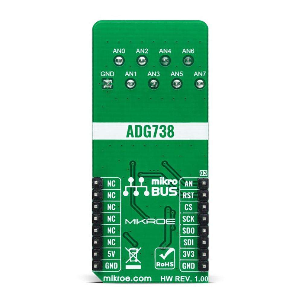
This table shows how the pinout on the Analog MUX 3 Click Board™ corresponds to the pinout on the mikroBUS™ socket (the latter shown in the two middle columns).
Notes | Pin | Pin | Notes | ||||
---|---|---|---|---|---|---|---|
Analog Signal | AN | 1 | AN | PWM | 16 | NC | |
Reset | RST | 2 | RST | INT | 15 | NC | |
SPI Chip Select | CS | 3 | CS | RX | 14 | NC | |
SPI Clock | SCK | 4 | SCK | TX | 13 | NC | |
SPI Data OUT | SDO | 5 | MISO | SCL | 12 | NC | |
SPI Data IN | SDI | 6 | MOSI | SDA | 11 | NC | |
Power Supply | 3.3V | 7 | 3.3V | 5V | 10 | 5V | Power Supply |
Ground | GND | 8 | GND | GND | 9 | GND | Ground |
ONBOARD SETTINGS AND INDICATORS
Label | Name | Default | Description |
---|---|---|---|
LD1 | PWR | - | Power LED Indicator |
JP1 | VCC SEL | Left | Logic Level Voltage Selection 3V3/5V: Left position 3V3, Right position 5V |
ANALOG MUX 3 CLICK ELECTRICAL SPECIFICATIONS
Description | Min | Typ | Max | Unit |
---|---|---|---|---|
Supply Voltage | 3.3 | - | 5 | V |
Analog Input Signal Range | 0 | - | 5 | V |
On-Resistance | - | - | 4.5 | Ω |
Operating Temperature Range | -40 | +25 | +105 | °C |
We provide a library for the Analog MUX 3 Click Board™ as well as a demo application (example), developed using MikroElektronika compilers. The demo can run on all the main MikroElektronika development boards.
The package can be downloaded/installed directly from NECTO Studio Package Manager(recommended way), downloaded from our LibStock™ or found on the mikroE Github account.
Library Description
This library contains API for Analog Mux 3 Click driver.
Key Functions
analogmux3_cfg_setup
- Config Object Initialization function.analogmux3_init
- Initialization function.analogmux3_default_cfg
- Click Default Configuration function.
Example Description
This is an example that demonstrates the use of the Analog MUX 3 click board. This application controls the multiplexing of a single input channel with an eight-channel matrix switch.
The demo application is composed of two sections :
void application_task ( void ) { for ( uint8_t ch_pos = ANALOGMUX3_SET_CHANNEL_0; ch_pos <= ANALOGMUX3_SET_CHANNEL_7; ch_pos++ ) { analogmux3_set_channel( &analogmux3, ch_pos ); Delay_ms( 1000 ); uint16_t analogmux3_an_value = 0; log_printf( &logger, " CHANNEL : AN%u rn", ch_pos ); log_printf( &logger, "- - - - - - - - - - - - - rn" ); if ( analogmux3_read_an_pin_value ( &analogmux3, &analogmux3_an_value ) != ADC_ERROR ) { log_printf( &logger, " ADC Value : %urn", analogmux3_an_value ); } float analogmux3_an_voltage = 0; if ( analogmux3_read_an_pin_voltage ( &analogmux3, &analogmux3_an_voltage ) != ADC_ERROR ) { log_printf( &logger, " AN Voltage : %.3f V rn", analogmux3_an_voltage ); } log_printf( &logger, "-------------------------rn" ); } } The full application code, and ready to use projects can be installed directly from NECTO Studio Package Manager(recommended way), downloaded from our LibStock™ or found on mikroE Github account.
Other mikroE Libraries used in the example:
- MikroSDK.Board
- MikroSDK.Log
- Click.AnalogMux3
Additional Notes and Information
Depending on the development board you are using, you may need a USB UART click, USB UART 2 click or RS232 click to connect to your PC, for development systems with no UART to USB interface available on the board. The terminal available in all MikroElektronika compilers, or any other terminal application of your choice, can be used to read the message.
MIKROSDK
The Analog MUX 3 Click Board™ is supported with mikroSDK - MikroElektronika Software Development Kit. To ensure proper operation of mikroSDK compliant Click board™ demo applications, mikroSDK should be downloaded from the LibStock and installed for the compiler you are using.
Frequently Asked Questions
Have a Question?
Be the first to ask a question about this.