Ladegerät 6 Click-Platine
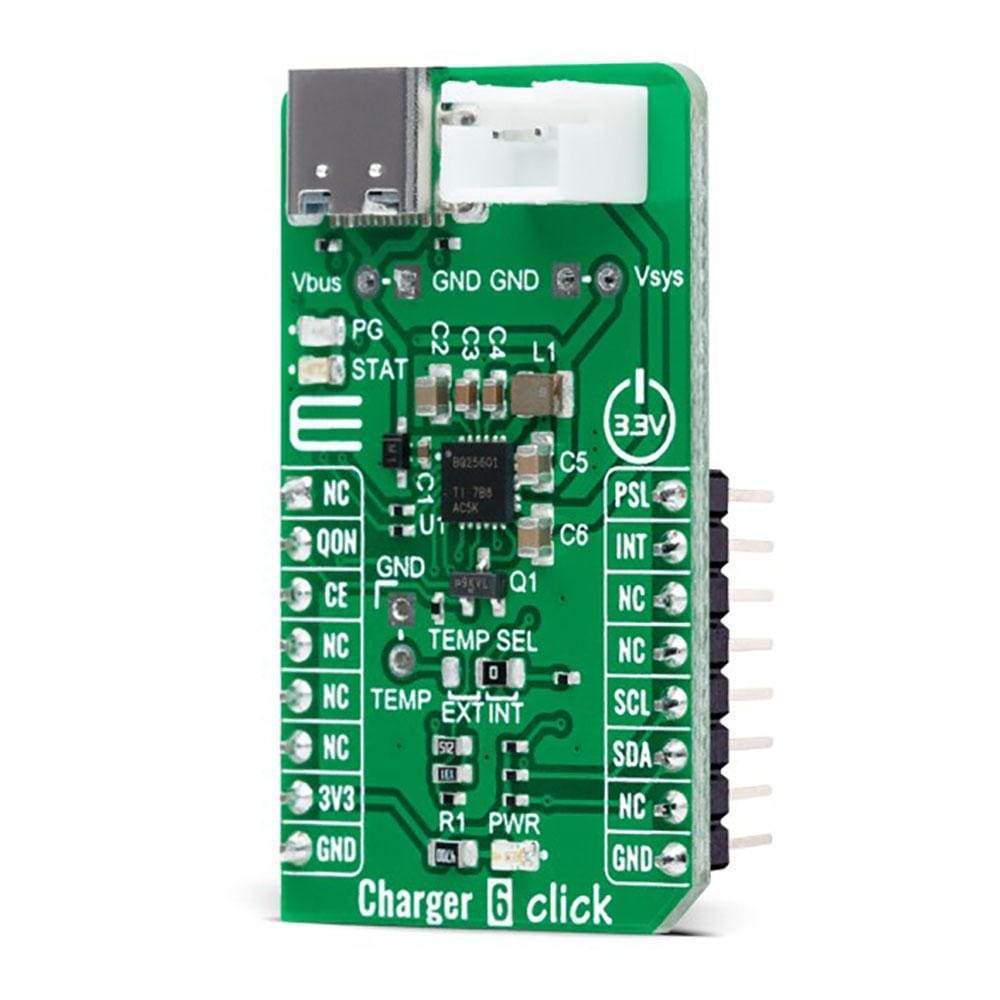
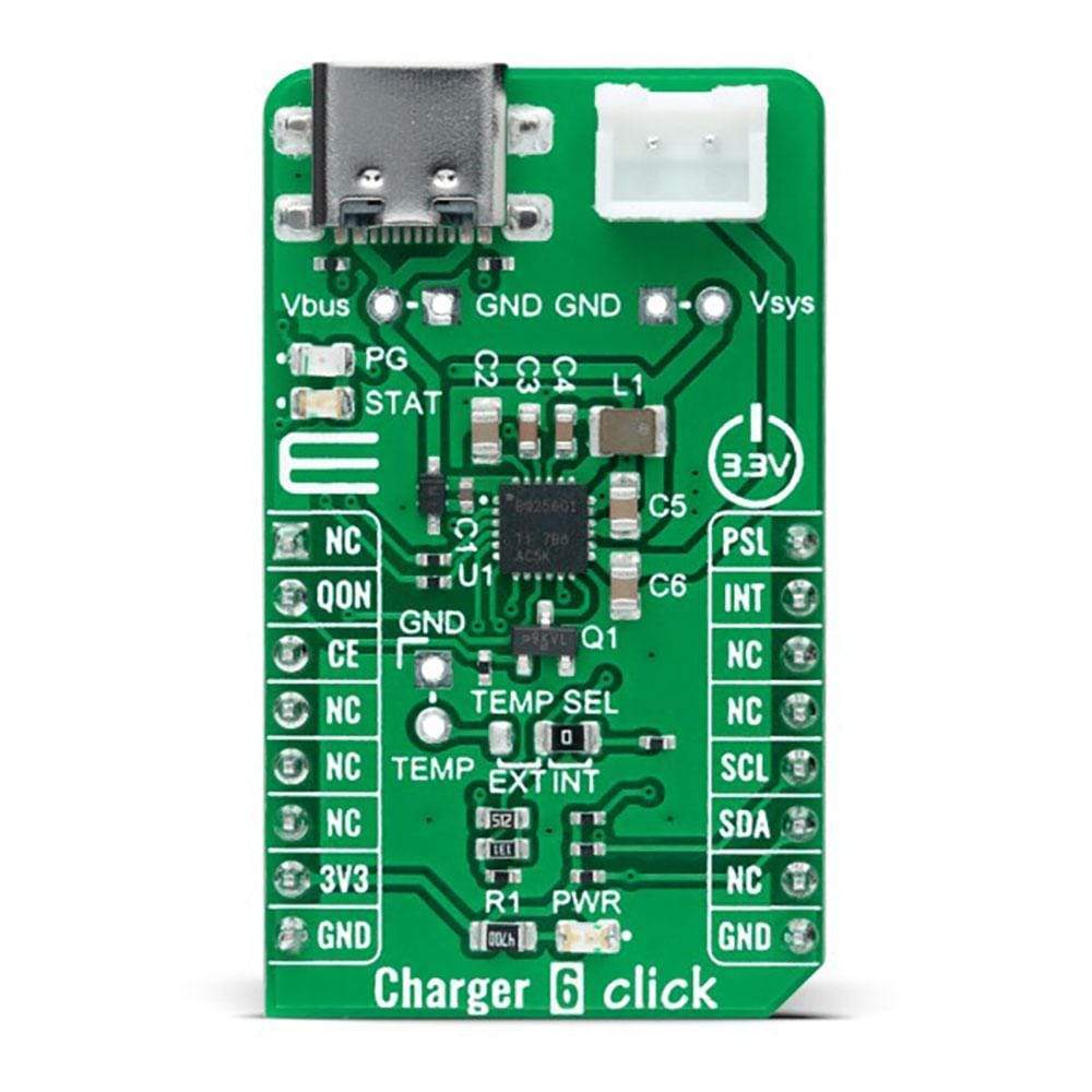
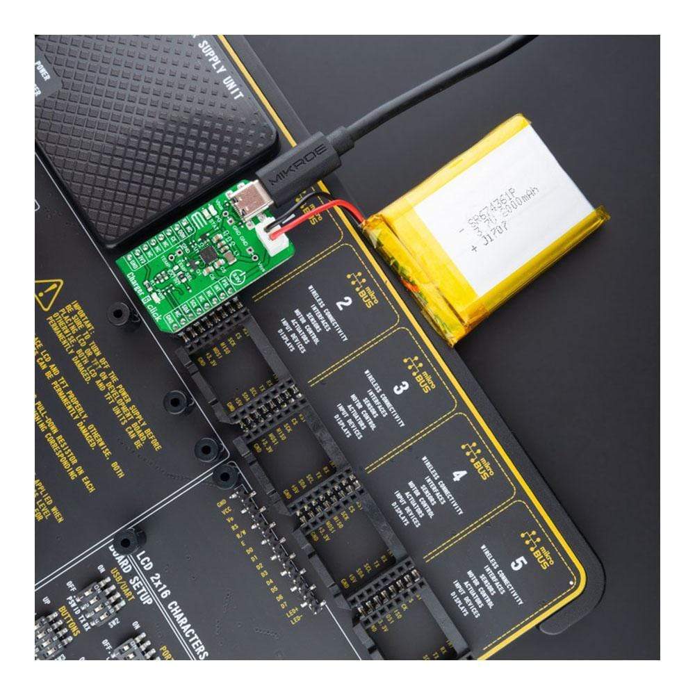
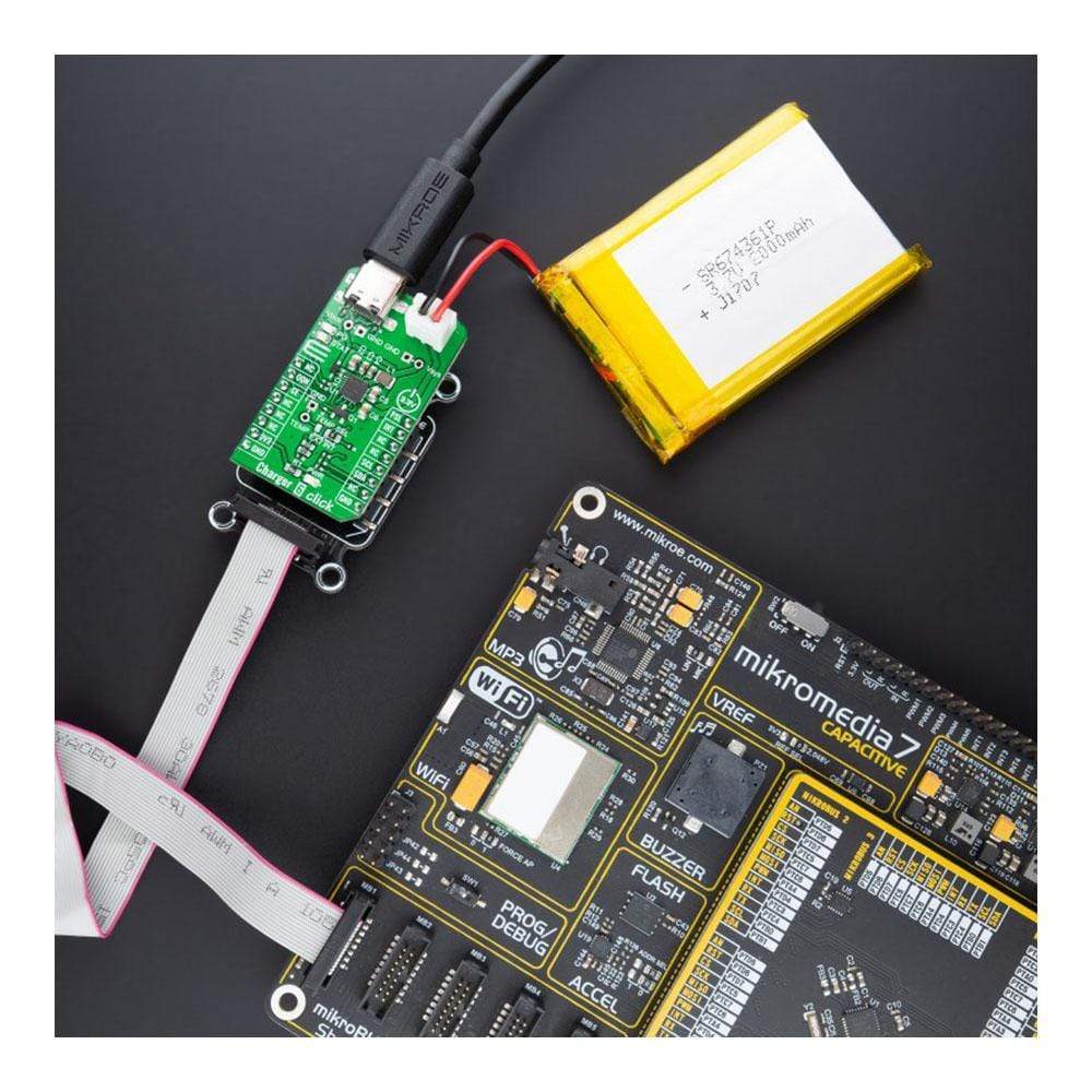
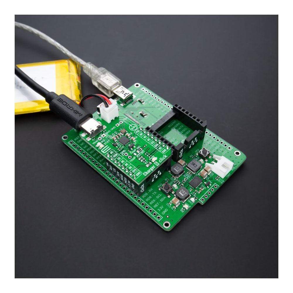
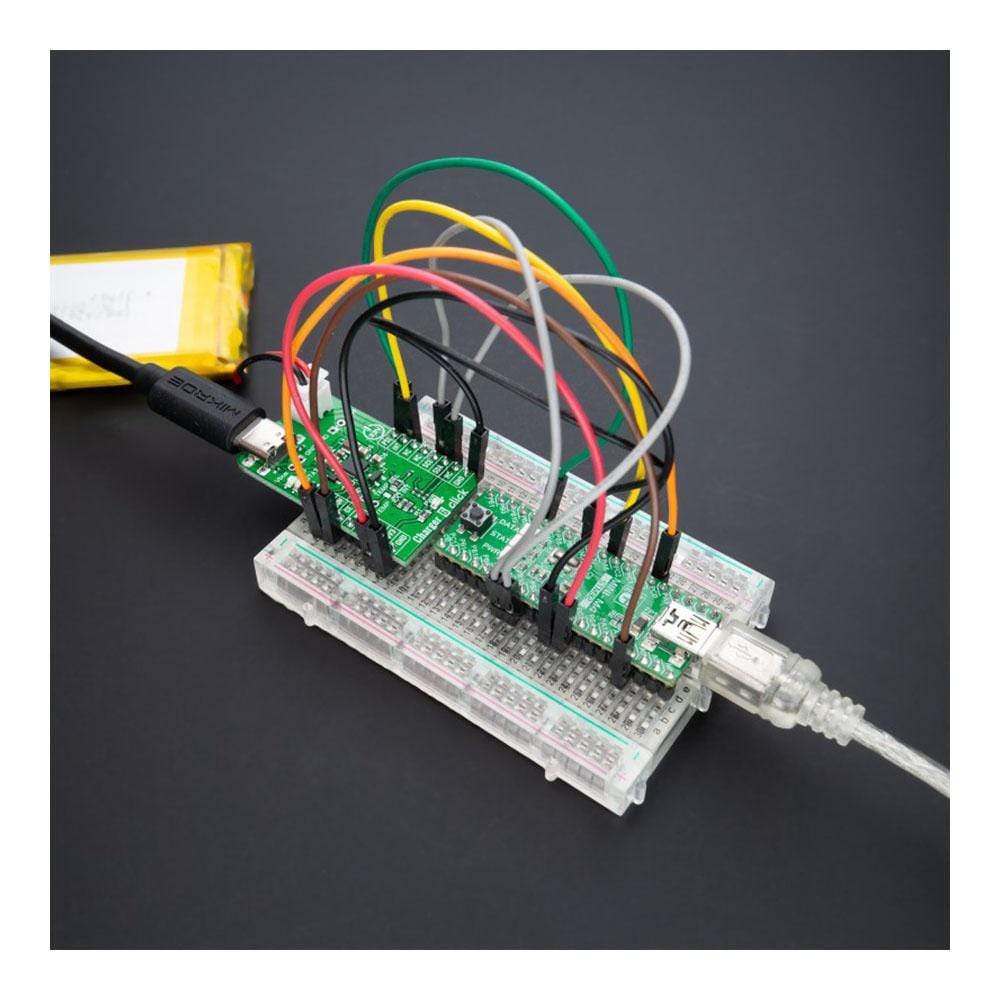
Das Charger 6 Click Board™ ist eine kompakte Zusatzplatine, die ein Einzelzellen-Akkuladegerät darstellt. Diese Platine verfügt über den BQ25601, ein I2C-gesteuertes Akkuladegerät für hohe Eingangsspannung und schmale DC-Strompfadverwaltung von Texas Instruments. Dieses Abwärtsladegerät unterstützt USB und ist für den USB-Spannungseingang optimiert. Der Strompfad mit niedriger Impedanz optimiert die Effizienz des Schaltbetriebs, verkürzt die Akkuladezeit und verlängert die Akkulebensdauer während der Entladung. Es verfügt außerdem über eine programmierbare Strombegrenzung, sodass es ein externes Netzteil mit einer Nennleistung von bis zu 13,5 V verwenden kann. Dieses Click Board™ eignet sich als Li-Ion- und Li-Polymer-Akkuladegerät für tragbare Geräte und Zubehör, Elektrowerkzeuge und mehr.
Der Charger 6 Click wird durch eine mikroSDK-kompatible Bibliothek unterstützt, die Funktionen enthält, die die Softwareentwicklung vereinfachen. Dieses Click Board™ wird als vollständig getestetes Produkt geliefert und ist bereit für den Einsatz auf einem System, das mit der mikroBUS™-Buchse ausgestattet ist.
How Does the Charger 6 Click Board™ work?
The Charger 6 Click Board™ as its foundation uses the BQ25601, a fast-charging solution for single-cell Li-Ion and Li-polymer battery with high input voltage suitable for a wide range of smartphones, tablets, and portable devices from Texas Instruments. The low impedance power path optimizes switch-mode operation efficiency, reduces battery charging time, and extends battery life during discharge. It is optimized for USB 5V voltage input, has a programmable current limiting based on the built-in USB interface, and allows the use of an external power supply from 3.9 to 13.5V. The BQ25601 also meets USB On-the-Go (OTG) operation power rating specification by supplying 5.15 V on the VBUS line with a constant current limit of up to 1.2A. The device provides automatic power path selection on the SYS line from the VBUS input source, battery, or both.
The power path management regulates the system slightly above battery voltage but does not drop below 3.5 V minimum system voltage. With this feature, the system maintains operation even when the battery is completely removed. When the input current limit or voltage limit is reached, the power path management automatically reduces the charge current to zero. As the system load increases, the power path discharges the battery until the system power requirement is met.
Charger 6 Click communicates with MCU using the standard I2C 2-Wire interface and supports both Standard and Fast Mode with a transfer rate of 100 and 400kbit/s. The I2C serial interface with charging and system settings makes this Click board™ a truly flexible solution. Also, it uses several GPIO pins, one of which is an interrupt pin, the INT pin of the mikroBUS™ socket, used as a 'fault' indicator. This pin sets immediately notifies the host when a fault occurs.
This Click board™ also uses two LED indicators, labelled as PG and STAT, used as power good and charging status indicator. PG indicates a good input source if the input voltage is above the SLEEP mode threshold and the current limit is above 30mA, while STAT reports the charging status and any fault conditions. CE pin routed to the CS pin on the mikroBUS™ socket enables battery charging process by setting this pin into a low logic state. PSEL pin routed to the PWM pin on the mikroBUS™ socket is used as a power source selection input and sets 500mA input current limit by pulling this pin high, otherwise set 2.4A input current limit by pulling this pin low. The BQ25601 also provides a QON pin, routed to the RST pin on the mikroBUS™ socket, for BATFET enable and reset control, to exit low-power mode or whole system reset function.
The charger provides a temperature monitoring feature selectable via jumper labelled as TEMP SEL, where the user can choose between external or internal modes of monitoring. For external mode, a single thermistor input for the battery temperature monitor is provided.
This Click board™ can be operated only with a 3.3V logic voltage level. The board must perform appropriate logic voltage level conversion before use with MCUs with different logic levels. However, the Click board™ comes equipped with a library containing functions and an example code that can be used, as a reference, for further development.
SPECIFICATIONS
Type | Battery charger |
Applications | Can be used for a Li-Ion and Li-polymer battery charger for portable devices and accessories, power tools, and more. |
On-board modules | BQ25601 - fast-charging solution for single-cell Li-Ion and Li-polymer battery with high input voltage suitable for a wide range of smartphones, tablets, and portable devices from Texas Instruments |
Key Features | High efficiency, USB On-The-Go feature, high battery discharge efficiency, accuracy, programmable input current limit, and more. |
Interface | I2C |
Compatibility | mikroBUS |
Click board size | M (42.9 x 25.4 mm) |
Input Voltage | 3.3V, External |
PINOUT DIAGRAM
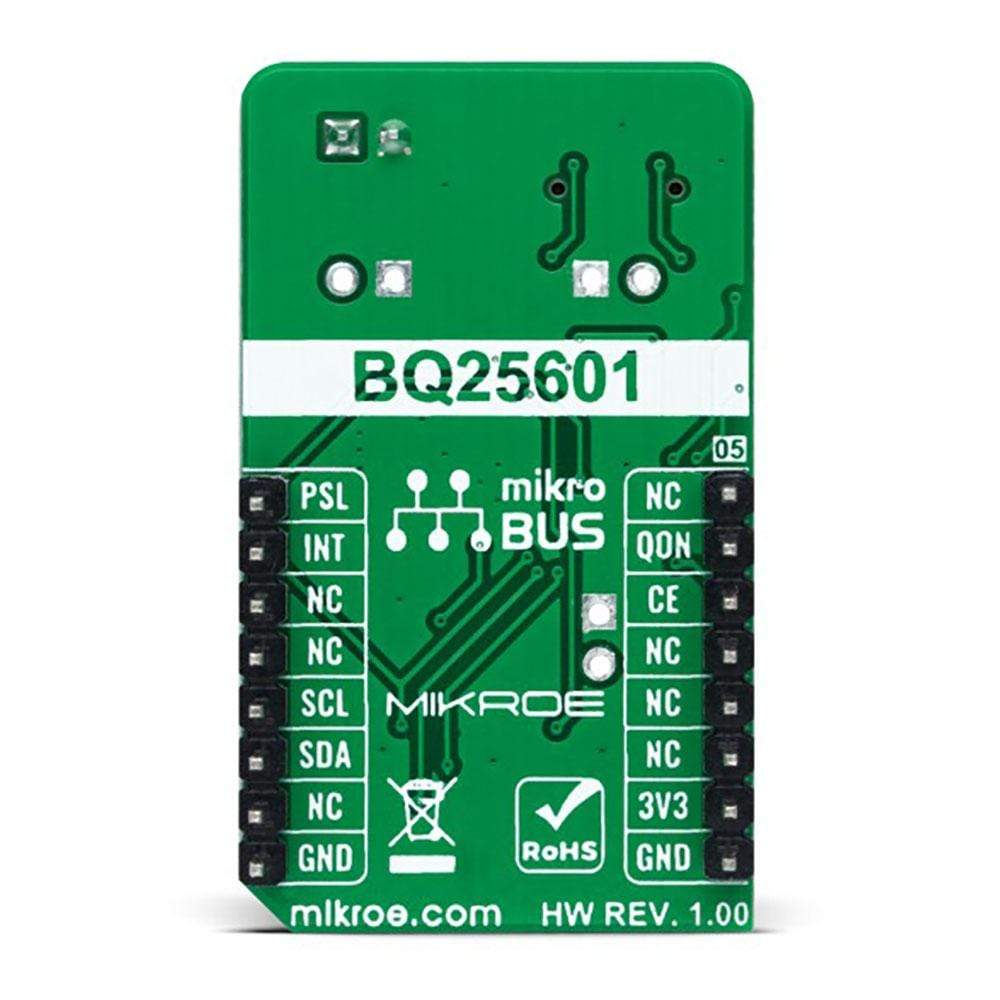
This table shows how the pinout on Charger 6 Click corresponds to the pinout on the mikroBUS™ socket (the latter shown in the two middle columns).
Notes | Pin | Pin | Notes | ||||
---|---|---|---|---|---|---|---|
NC | 1 | AN | PWM | 16 | PSL | Power Source Selection | |
Reset Control | QON | 2 | RST | INT | 15 | INT | Interrupt |
Charging Process Enable | CS | 3 | CS | RX | 14 | NC | |
NC | 4 | SCK | TX | 13 | NC | ||
NC | 5 | MISO | SCL | 12 | SCL | I2C Clock | |
NC | 6 | MOSI | SDA | 11 | SDA | I2C Data | |
Power Supply | 3.3V | 7 | 3.3V | 5V | 10 | NC | |
Ground | GND | 8 | GND | GND | 9 | GND | Ground |
ONBOARD SETTINGS AND INDICATORS
Label | Name | Default | Description |
---|---|---|---|
LD1 | PWR | - | Power LED Indicator |
LD2 | STAT | - | Charging Status LED Indicator |
LD3 | PG | - | Power Good LED Indicator |
JP1 | TEMP SEL | Left | Temperature Monitoring Selection EXT/INT: Left position EXT, Right position INT |
CN2 | VBUS | Unpopulated | External Power Supply Connector |
CN3 | VSYS | Unpopulated | Converters Output Voltage Connector |
CN4 | TEMP | Unpopulated | External Thermistor Connector |
CHARGER 6 CLICK ELECTRICAL SPECIFICATIONS
Description | Min | Typ | Max | Unit |
---|---|---|---|---|
Supply Voltage VCC | - | 3.3 | - | V |
Supply Voltage VBAT | 3.9 | - | 13.5 | V |
Output Voltage VSYS | 3.68 | - | 4.45 | V |
Battery Charging Voltage | 3.856 | - | 4.624 | V |
Battery Charging Output Current | 0 | - | 3 | A |
Operating Temperature Range | -40 | +25 | +85 | °C |
Software Support
We provide a library for the Charger 6 Click Board™ as well as a demo application (example), developed using MikroElektronika compilers. The demo can run on all the main MikroElektronika development boards.
The package can be downloaded/installed directly from NECTO Studio Package Manager(recommended way), downloaded from our LibStock™ or found on the mikroE Github account.
Library Description
This library contains API for Charger 6 Click Board™ driver.
Key Functions
charger6_cfg_setup
- Config Object Initialization function.charger6_init
- Initialization function.charger6_default_cfg
- Click Default Configuration function.
Example Description
This library contains an API for the Charger 6 Click driver. The library contains drivers to enable/disable battery charging, set current limit, set system min voltage, set the fast charge current, set charge voltage, etc.
The application is composed of three sections :
void application_task ( void ) { charger6_get_status( &charger6, &chg_status ); Delay_ms( 100 ); display_power_good_status( ); Delay_ms( 100 ); display_chrg_status( ); Delay_ms( 100 ); display_bat_status( ); Delay_ms( 100 ); display_chrg_fault_status( ); Delay_ms( 100 ); display_vsys_status( ); log_printf( &logger, "-------------------------------rn" ); Delay_ms( 2000 ); }
The full application code, and ready to use projects can be installed directly from NECTO Studio Package Manager(recommended way), downloaded from our LibStock™ or found on mikroE Github account.
Other mikroE Libraries used in the example:
- MikroSDK.Board
- MikroSDK.Log
- Click.Charger6
Additional Notes and Information
Depending on the development board you are using, you may need a USB UART click, USB UART 2 click or RS232 click to connect to your PC, for development systems with no UART to USB interface available on the board. The terminal available in all MikroElektronika compilers, or any other terminal application of your choice, can be used to read the message.
MIKROSDK
This Click board™ is supported with mikroSDK - MikroElektronika Software Development Kit. To ensure proper operation of mikroSDK compliant Click board™ demo applications, mikroSDK should be downloaded from the LibStock and installed for the compiler you are using.
Ladegerät 6 Click-Platine
Frequently Asked Questions
Have a Question?
Be the first to ask a question about this.