SolidSwitch Click-Platine
Overview
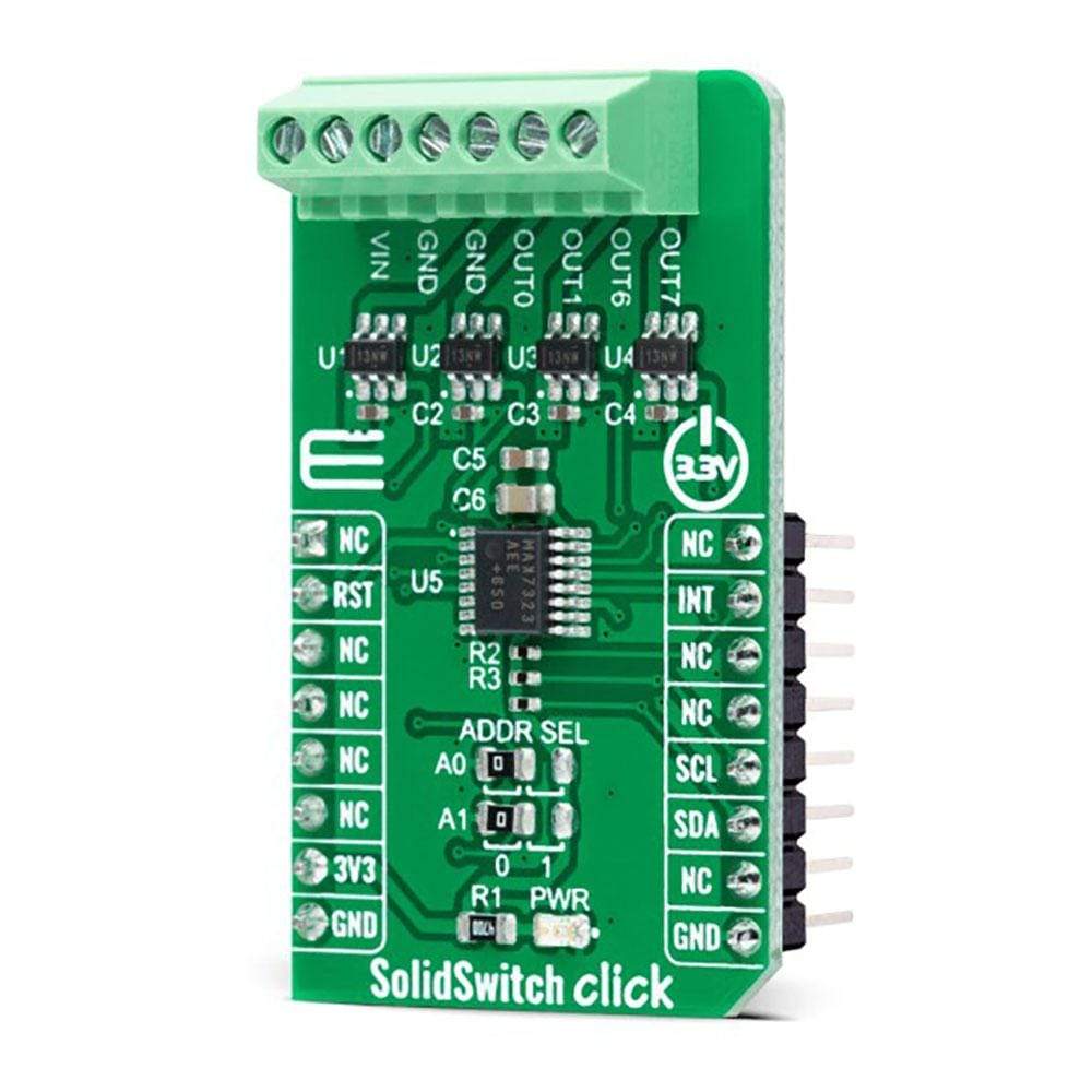
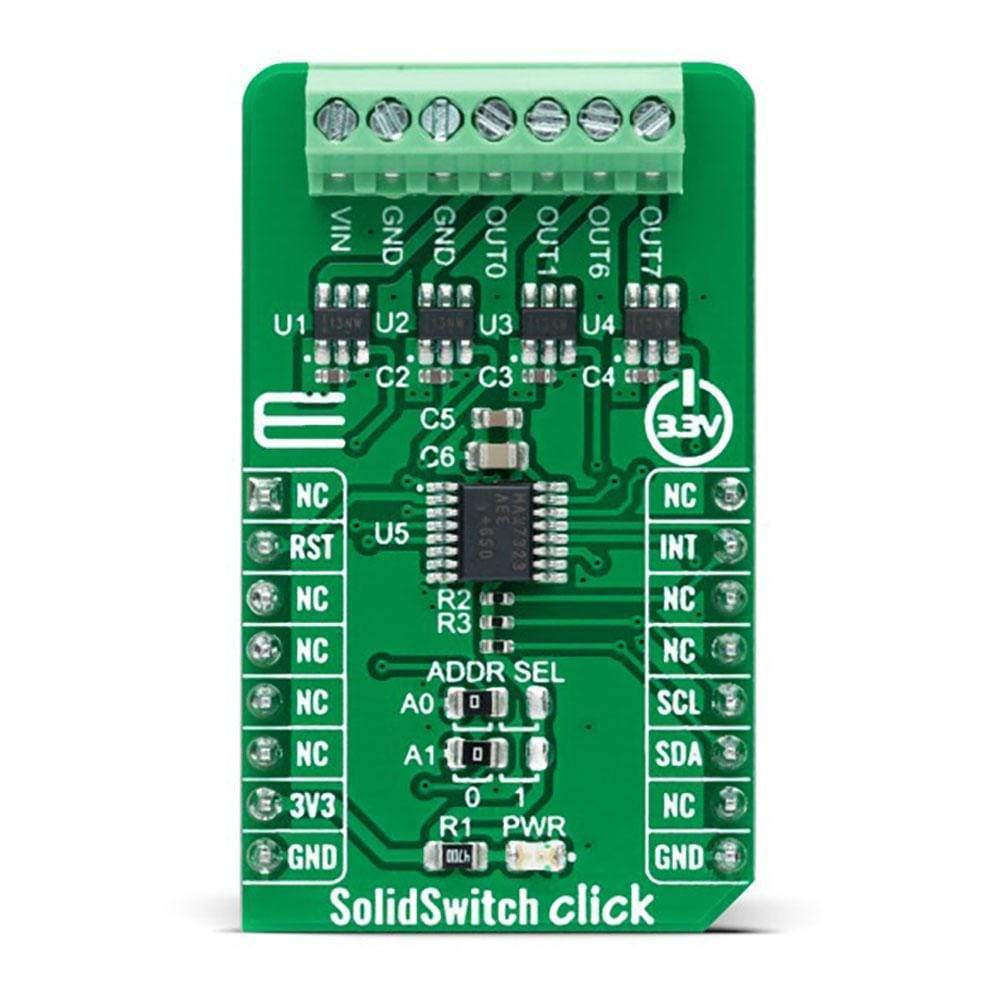
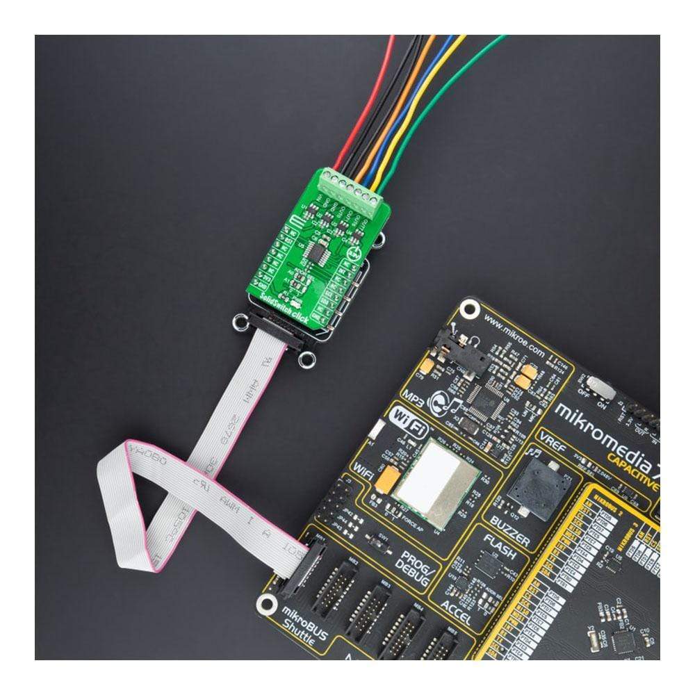
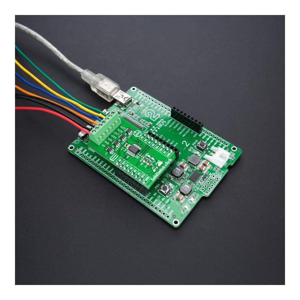
Das SolidSwitch Click Board™ ist eine kompakte Zusatzplatine, die Lastschaltergeräte enthält. Diese Platine verfügt über den TPS22918, vier einkanalige Lastschalter von Texas Instruments. Jeder Schalter enthält einen N-Kanal-MOSFET, der über einen Eingangsspannungsbereich von bis zu 5,5 V betrieben werden kann und einen maximalen Dauerstrom von 2 A unterstützen kann. Die Schalter werden über einen EIN/AUS-Eingang gesteuert, der von MAX7323 ausgeführt wird, einem I2C-konfigurierbaren Port-Expander, der direkt mit Niederspannungs-Steuersignalen verbunden werden kann. Dieses Click Board™ ist für Industriesysteme, Set-Top-Boxen, elektronische Waagen und verschiedene andere Anwendungen geeignet.
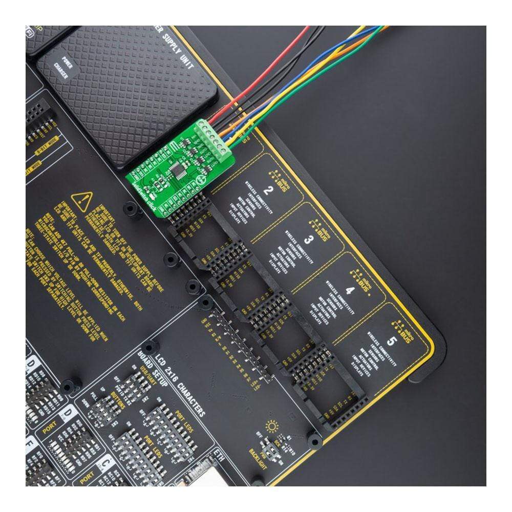
Das SolidSwitch Click Board™ wird durch eine mikroSDK-kompatible Bibliothek unterstützt, die Funktionen enthält, die die Softwareentwicklung vereinfachen. Dieses Click Board™ wird als vollständig getestetes Produkt geliefert und ist bereit für den Einsatz auf einem System, das mit der mikroBUS™-Buchse ausgestattet ist.
How Does The SolidSwitch Click Board™ Work?
The SolidSwitch Click Board™ is based on the TPS22918, a 5.5V 2A load switch from Texas Instruments. To reduce voltage drop for low voltage and high current rails, every TPS22918 implements a low resistance N-channel MOSFET, reducing the drop-out voltage across the device. An ON/OFF input on the ON pin of the TPS22918 controls the switches. The ON pin is compatible with the standard GPIO logic threshold and can be used with any MCU with 1V or higher GPIO voltage. That's why the control of all switches is established via the port expander, the MAX7323.
This Click board™ is designed to operate from an external supply voltage range from 1V to 5.5V. The TPS22918 works regardless of power sequencing order. The order in which voltages are applied to the VIN terminal and ON pin of the load switch will not damage the device as long as the voltages do not exceed the absolute maximum operating conditions.
The SolidSwitch Click Board™ communicates with MCU through the MAX7323 port expander using the standard I2C 2-Wire interface with a frequency of up to 400kHz. It also has two address pins (A0 and A1) programmed by the user to determine the value of the last two LSBs of the slave address, selected by onboard SMD jumpers labelled as ADDR SEL to an appropriate position marked as 0 and 1, allowing selection of the slave address LSBs. Also, this Click board™ has a Reset pin, routed to the RST pin on the mikroBUS™ socket, which clears the serial interface in case of a bus lockup, terminating any serial transaction to or from the MAX7323.
Also, it uses an additional pin, the INT pin of the mikroBUS™ socket, which automatically flags data changes on any of the I/O ports of the MAX7323 used as inputs. The interrupt output INT and all transition flags are deasserted when the MAX7323 is accessed through the serial interface.
The SolidSwitch Click Board™ can be operated only with a 3.3V logic voltage level. The board must perform appropriate logic voltage level conversion before use with MCUs with different logic levels. However, the Click board™ comes equipped with a library containing functions and an example code that can be used, as a reference, for further development.
SPECIFICATIONS
Type | Relay |
Applications | Can be used for industrial systems, set-top boxes, electronic point of scale, and various other applications. |
On-board modules | TPS22918 - 5.5V 2A load switch from Texas Instruments |
Key Features | Four integrated single channel load switches, flexible design, 2A maximum switch current, and more. |
Interface | I2C |
Compatibility | mikroBUS |
Click board size | M (42.9 x 25.4 mm) |
Input Voltage | 3.3V,External |
PINOUT DIAGRAM
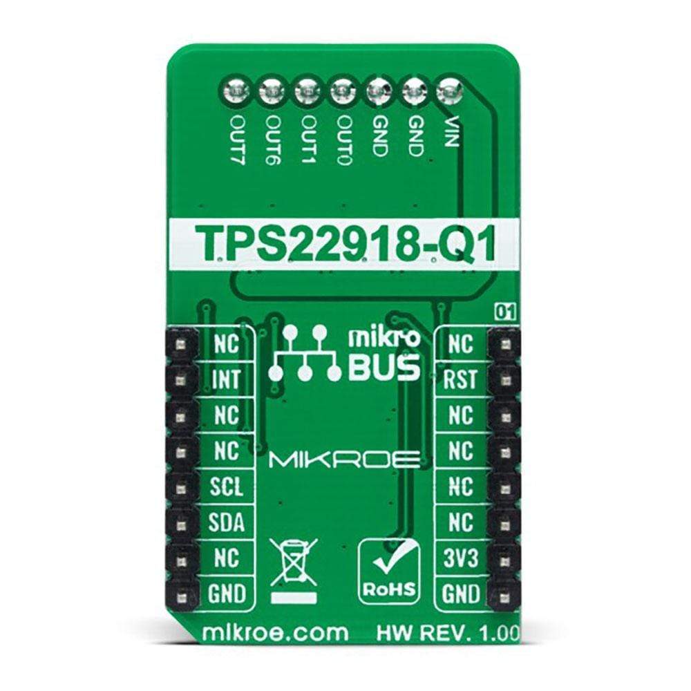
This table shows how the pinout of the SolidSwitch Click Board™ corresponds to the pinout on the mikroBUS™ socket (the latter shown in the two middle columns).
Notes | Pin | Pin | Notes | ||||
---|---|---|---|---|---|---|---|
NC | 1 | AN | PWM | 16 | NC | ||
Reset | RST | 2 | RST | INT | 15 | INT | Interrupt |
NC | 3 | CS | RX | 14 | NC | ||
NC | 4 | SCK | TX | 13 | NC | ||
NC | 5 | MISO | SCL | 12 | SCL | I2C Clock | |
NC | 6 | MOSI | SDA | 11 | SDA | I2C Data | |
Power Supply | 3.3V | 7 | 3.3V | 5V | 10 | NC | |
Ground | GND | 8 | GND | GND | 9 | GND | Ground |
ONBOARD SETTINGS AND INDICATORS
Label | Name | Default | Description |
---|---|---|---|
LD1 | PWR | - | Power LED Indicator |
JP1-JP2 | ADDR SEL | Left | I2C Address Selection 0/1: Left position 0, Right position 1 |
SOLIDSWITCH CLICK ELECTRICAL SPECIFICATIONS
Description | Min | Typ | Max | Unit |
---|---|---|---|---|
Supply Voltage VCC | - | 3.3 | - | V |
Supply Voltage VIN | 1 | - | 5.5 | V |
Maximum Output Current | - | - | 2 | A |
Maximum On-Resistance | - | - | 52 | mΩ |
Operating Temperature Range | -40 | +25 | +105 | °C |
Software Support
We provide a library for the SolidSwitch Click Board™ as well as a demo application (example), developed using MikroElektronika compilers. The demo can run on all the main MikroElektronika development boards.
The package can be downloaded/installed directly from NECTO Studio The package Manager (recommended way), downloaded from our LibStock™ or found on the mikroE Github account.
Library Description
This library contains API for the SolidSwitch Click Board™ driver.
Key Functions
solidswitch_cfg_setup
- Config Object Initialization function.solidswitch_init
- Initialization function.solidswitch_default_cfg
- Click Default Configuration function.
Example Description
This example demonstrates the use of the SolidSwitch Click Board™.
The demo application is composed of two sections :
void application_task ( void ) { solidswitch_write_single ( &solidswitch, SOLIDSWITCH_ENABLE_OUT0 | SOLIDSWITCH_ENABLE_OUT1 ); solidswitch_display_enabled_channels( ); Delay_ms ( 3000 ); solidswitch_write_single ( &solidswitch, SOLIDSWITCH_ENABLE_OUT6 | SOLIDSWITCH_ENABLE_OUT7 ); solidswitch_display_enabled_channels( ); Delay_ms ( 3000 ); solidswitch_write_single ( &solidswitch, SOLIDSWITCH_ENABLE_ALL_OUTPUTS ); solidswitch_display_enabled_channels( ); Delay_ms ( 3000 ); solidswitch_write_single ( &solidswitch, SOLIDSWITCH_DISABLE_ALL_OUTPUTS ); solidswitch_display_enabled_channels( ); Delay_ms ( 3000 ); }
The full application code, and ready to use projects can be installed directly from NECTO Studio The package Manager (recommended), downloaded from our LibStock™ or found on mikroE Github account.
Other mikroE Libraries used in the example:
- MikroSDK.Board
- MikroSDK.Log
- Click.SolidSwitch
Additional Notes and Information
Depending on the development board you are using, you may need USB UART Click Board™, USB UART 2 Click Board™ or RS232 Click Board™ to connect to your PC, for development systems with no UART to USB interface available on the board. The terminal available in all MikroElektronika compilers, or any other terminal application of your choice, can be used to read the message.
MIKROSDK
The SolidSwitch Click Board™ is supported with mikroSDK - MikroElektronika Software Development Kit. To ensure proper operation of mikroSDK compliant Click board™ demo applications, mikroSDK should be downloaded from the LibStock and installed for the compiler you are using.
Frequently Asked Questions
Have a Question?
Be the first to ask a question about this.