

Mikroelektronika d.o.o.
Opto 5 Click-Platine
Opto 5 Click-Platine
SKU: MIKROE-4476
Verfügbarkeit für Abholungen konnte nicht geladen werden


Overview
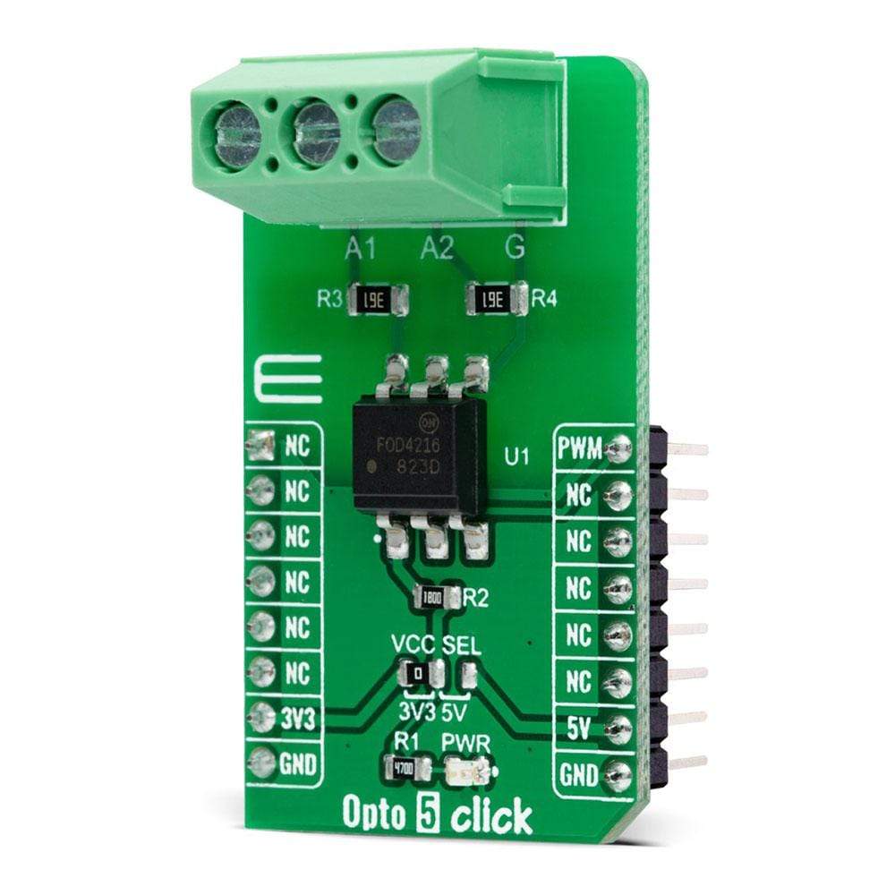
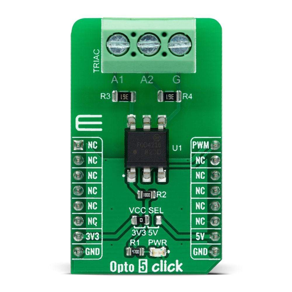
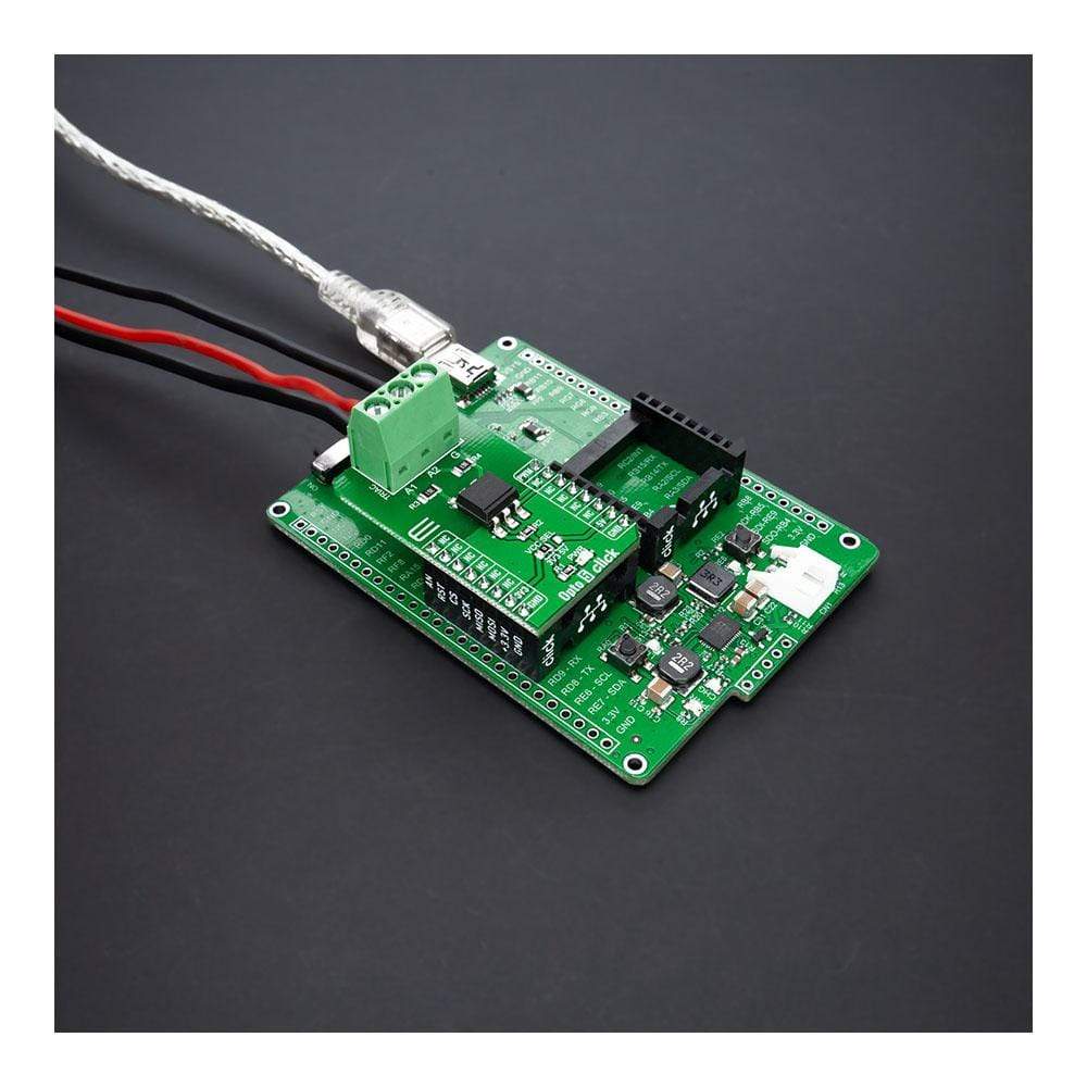
The Opto 5 Click Board™ is a compact add-on board that provides uncomplicated safety isolation from the high voltage. This board features the FOD4216, a random phase snubber-less Triac driver from ON Semiconductor. The FOD4216 consists of an infrared emitting diode coupled to a hybrid random phase triac formed with two inverse parallel SCRs, which creates the triac function capable of driving discrete triacs. It utilizes a high efficiency infrared emitting diode that offers an improved trigger sensitivity. This Click Board™ is suitable for applications like high voltage AC switching where there is a need to protect and electrically isolate two circuits in a switching application.
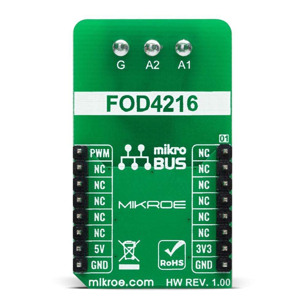
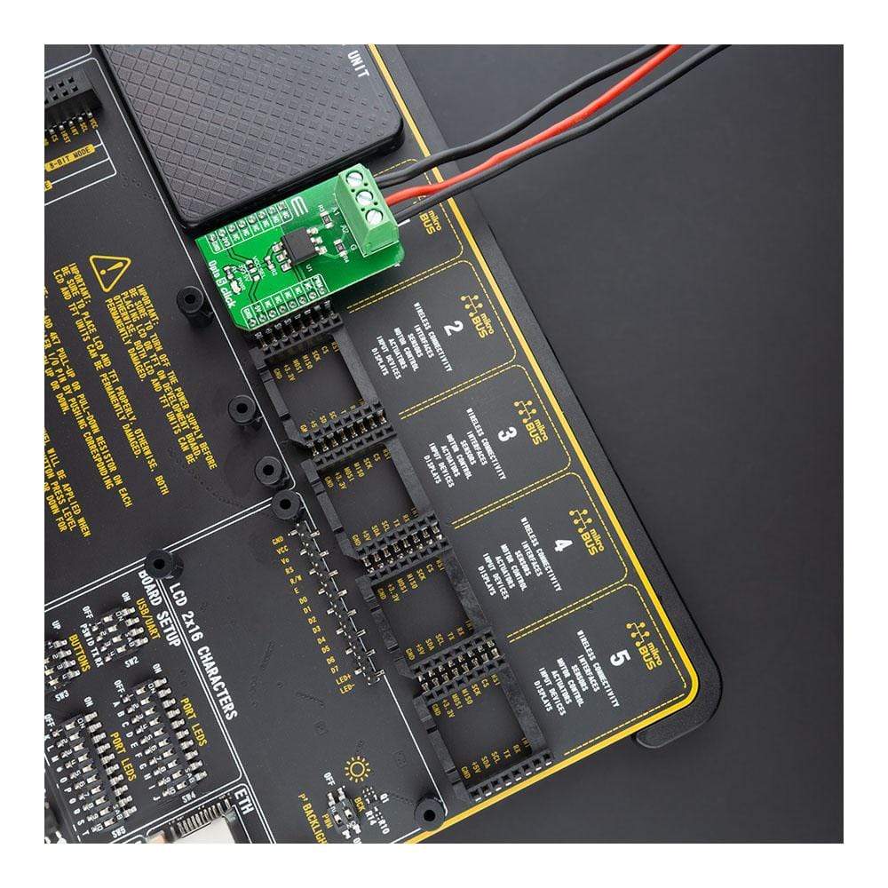
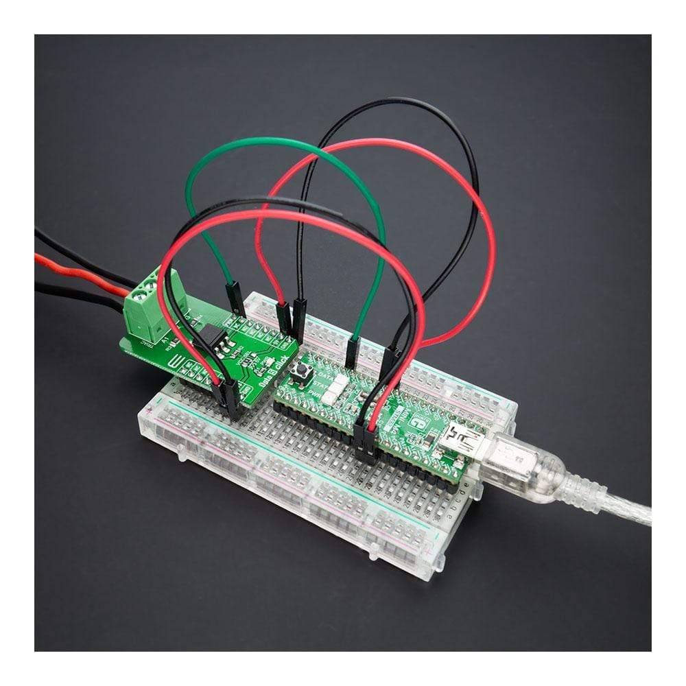
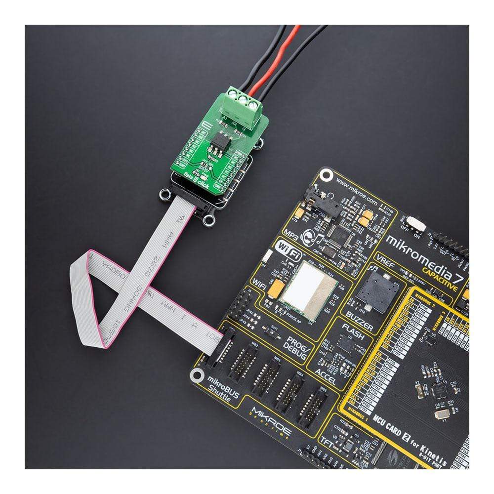
The Opto 5 Click Board™ is supported by a mikroSDK compliant library, which includes functions that simplify software development. This Click Board™ comes as a fully tested product, ready to be used on a system equipped with the mikroBUS™ socket.
Downloads
Der Opto 5 Click Board™ ist eine kompakte Zusatzplatine, die unkomplizierte Sicherheitsisolierung von Hochspannung bietet. Diese Platine verfügt über den FOD4216, einen Zufallsphasen-Triac-Treiber ohne Snubber von ON Semiconductor. Der FOD4216 besteht aus einer Infrarot-Emitterdiode, die mit einem hybriden Zufallsphasen-Triac gekoppelt ist, der aus zwei umgekehrt parallelen SCRs besteht, wodurch die Triac-Funktion entsteht, die diskrete Triacs ansteuern kann. Es verwendet eine hocheffiziente Infrarot-Emitterdiode, die eine verbesserte Triggerempfindlichkeit bietet. Dieses Click Board™ ist für Anwendungen wie Hochspannungs-Wechselstromschaltung geeignet, bei denen zwei Schaltkreise in einer Schaltanwendung geschützt und elektrisch isoliert werden müssen.
Das Opto 5 Click Board™ wird durch eine mikroSDK-kompatible Bibliothek unterstützt, die Funktionen enthält, die die Softwareentwicklung vereinfachen. Dieses Click Board™ wird als vollständig getestetes Produkt geliefert und ist bereit für den Einsatz auf einem System, das mit der mikroBUS™-Buchse ausgestattet ist.
| General Information | |
|---|---|
Part Number (SKU) |
MIKROE-4476
|
Manufacturer |
|
| Physical and Mechanical | |
Weight |
0.021 kg
|
| Other | |
EAN |
8606027381690
|
Frequently Asked Questions
Have a Question?
Be the first to ask a question about this.