NB IoT 5 Click-Platine
Overview
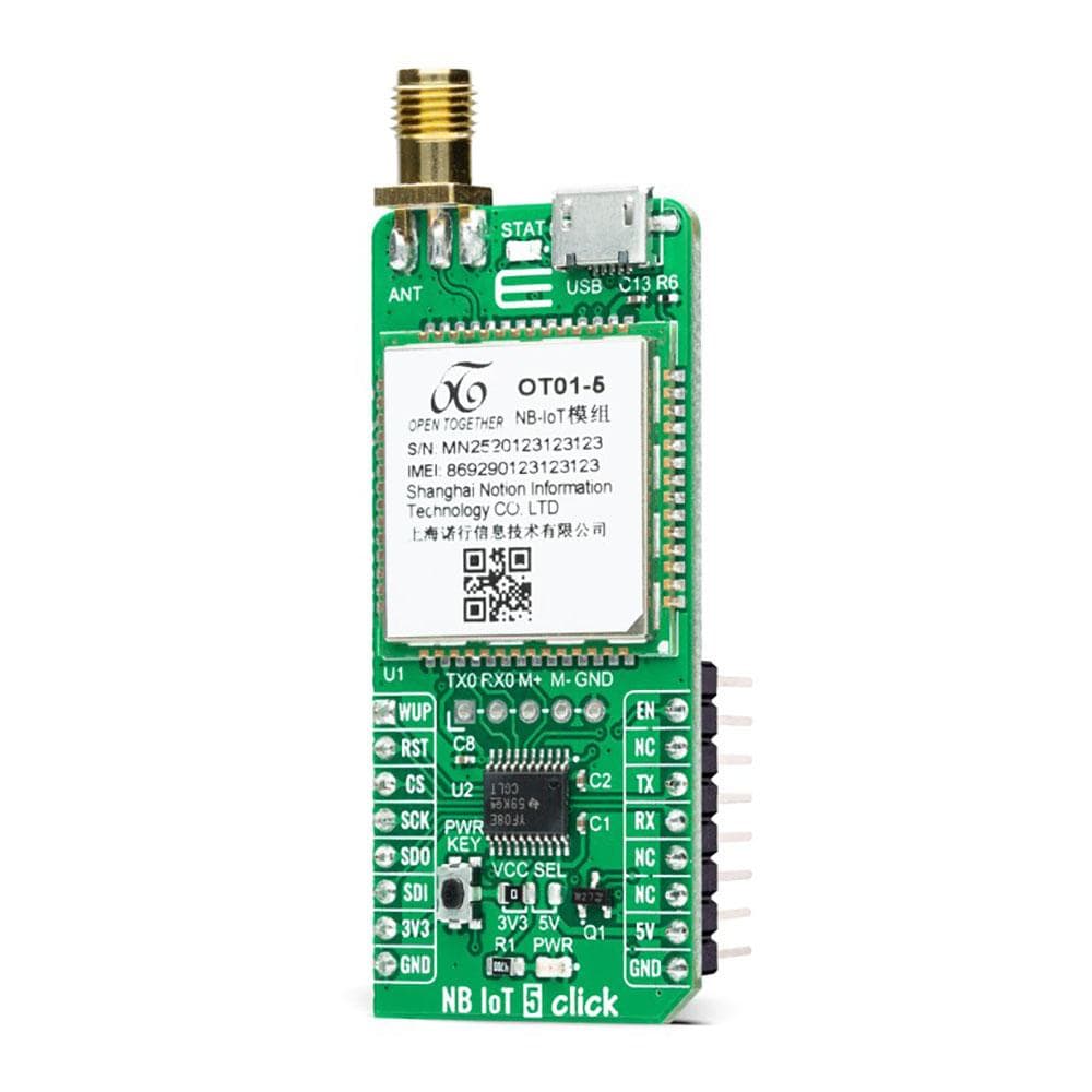
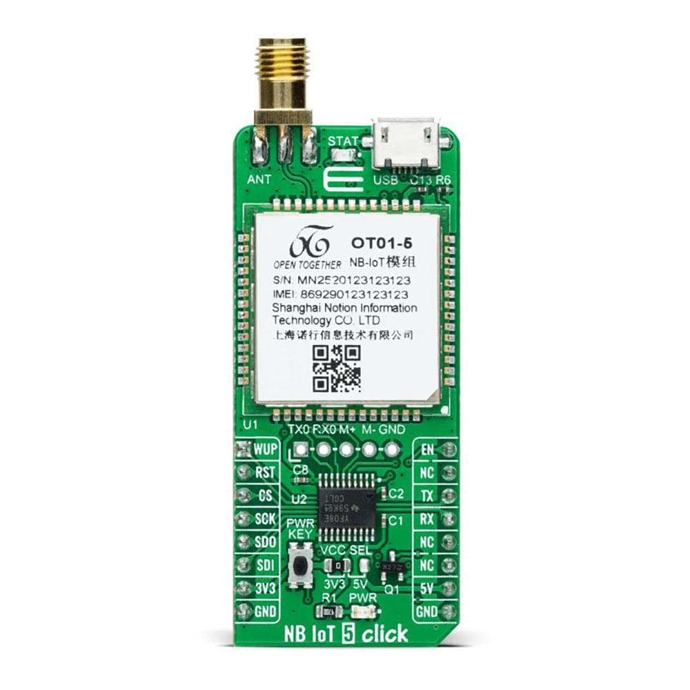
Das NB IoT 5 Click Board™ ist eine kompakte Zusatzplatine, die sich als universelle drahtlose Schmalband-Kommunikationslösung für das Internet der Dinge eignet. Diese Platine verfügt über das OT01-5, ein leistungsstarkes NB-IoT-Modul mit extrem niedrigem Stromverbrauch, das eine Batterielebensdauer von etwa zehn Jahren von Notion ermöglicht. Es unterstützt eine breite Palette von Frequenzbändern fast weltweit. Es bietet serielle Schnittstellen, UART und SPI, mit Protokollstapeln wie UDP/TCP, CoAP, LWM2M und anderen. Es bietet eine Alternative zu ähnlichen Low Power Wide Area Network (LPWAN)-Lösungen. Dieses Click Board™ eignet sich für viele IoT-Anwendungen wie intelligente Gas-/Wasserzähler, Informationserfassung, Sicherheitsüberwachung, Smart City/Home und andere Anwendungen.
Das NB IoT 5 Click Board™ wird durch eine mikroSDK-kompatible Bibliothek unterstützt, die Funktionen enthält, die die Softwareentwicklung vereinfachen. Dieses Click Board™ ist ein gründlich getestetes Produkt und kann auf einem System verwendet werden, das mit der mikroBUS™-Buchse ausgestattet ist.
How Does The NB IoT 5 Click Board™ Work?
The NB IoT 5 Click Board™ as its foundation uses the OT01-5, a high-performance narrow-band Internet of Things universal wireless communication module with meagre power consumption allowing battery life of about ten years from Notion. It supports a broad range of frequency bands worldwide, such as 1 / 2 / 3 / 5 / 8 / 19 / 20 of 3GPP R13 (NB1) and R14 (NB2). It also provides several interfaces, UART, SPI, and protocol stacks such as UDP/TCP, CoAP, LWM2M, and others. In addition to motor driver inside-design, these protocols allow data and SMS transfer using the NB technology. This module is perfect for building IoT applications and smart gas and water meters without an external microcontroller unit.
There are two ways to turn on this Click board™, through EN pin on the mikroBUS™ socket or by pressing the PWRKEY button for a period longer than 3 seconds. The onboard push-button labelled PWRKEY routed to the PWM pin on the mikroBUS™ socket represents the Ignition (Power-On) button. This feature is shown by the yellow diode labelled as STAT used to indicate the device's Operational Status.
The NB IoT 5 Click Board™ communicates with MCU using the UART interface as its default communication protocol with the option for the users to use another interface such as SPI if they want to configure the module and write the library by themselves. It supports automatic baud rate detection, operates at 115200 bps by default configuration, and is used for data transmission and exchanging AT commands with the host MCU. Also, it has an additional header used for firmware upgrades, software debugging, log capturing, or even as a motor drive.
In addition to these features, the OT01-5 also uses several GPIO pins connected to the mikroBUS™ socket. The WUP pin routed on the AN pin of the mikroBUS™ represents the Wake-up function used for waking up the device, while the RST pin on the mikroBUS™ socket can perform the Hardware Reset function by putting this pin in a logic low state. This Click board™ also has the micro USB connector allowing the module to be powered and configured by a personal computer.
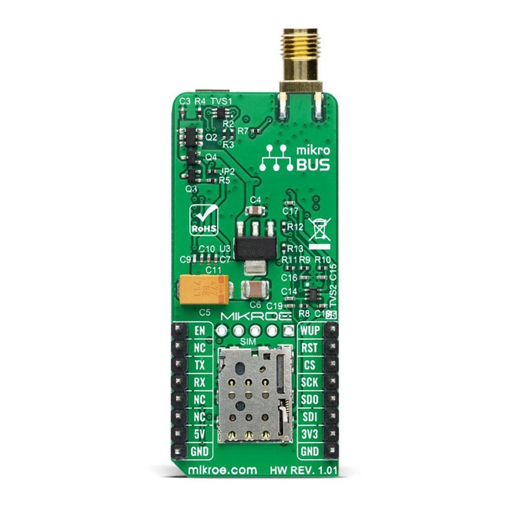
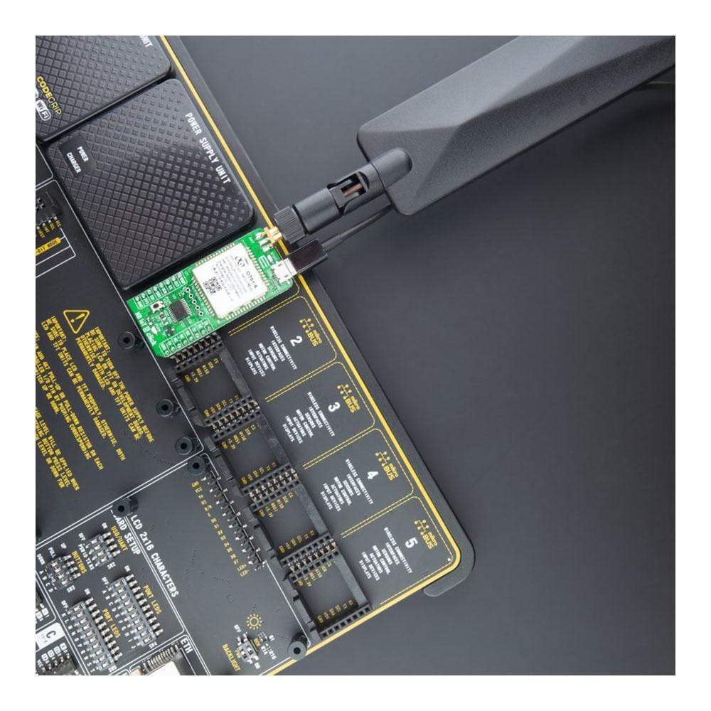
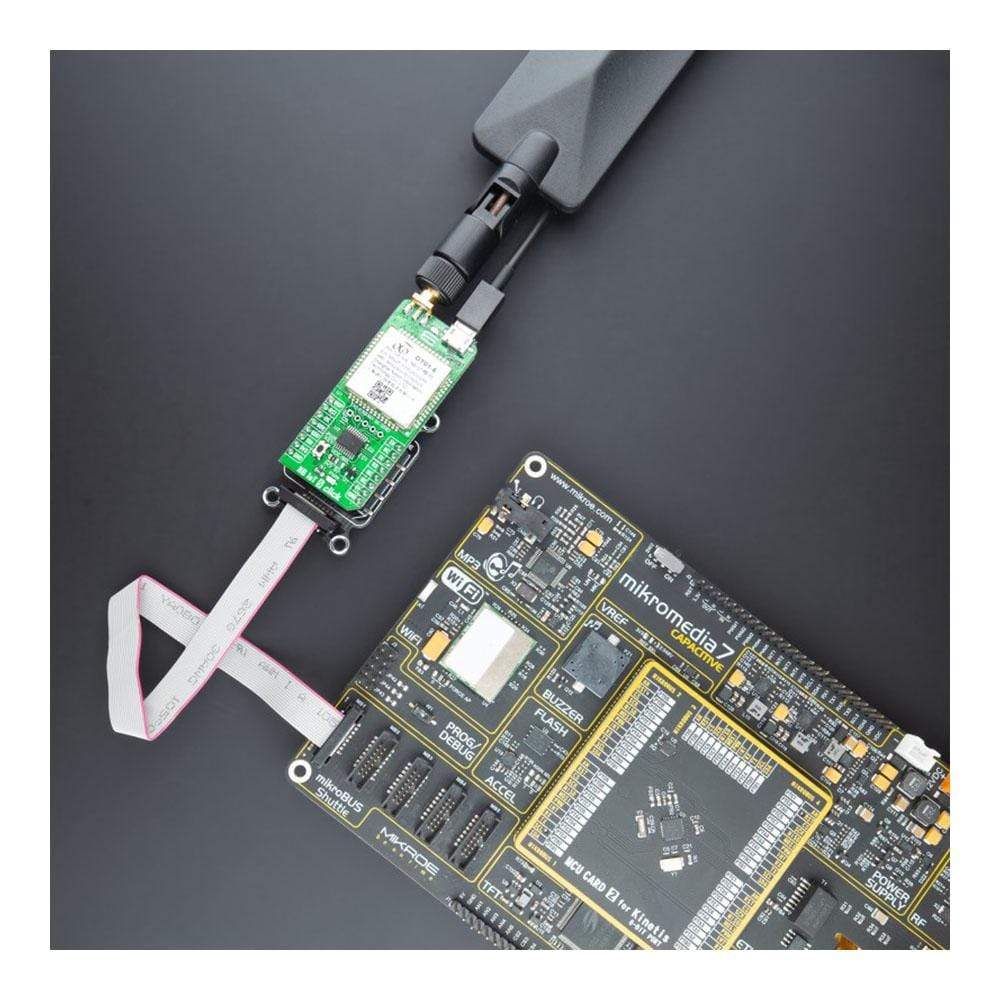
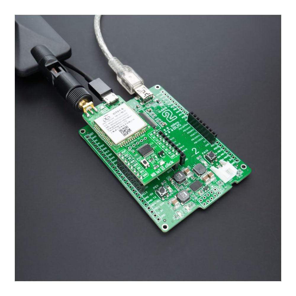
The NB IoT 5 Click Board™ possesses the SMA antenna connector with an impedance of 50Ω. This Click board™ can use it to connect the appropriate antenna, such as the LTE Flat Rotational Antenna that MikroE has in its offer. Besides the SMA connector, it also has a Nano-SIM card slot that provides multiple connections and interface options.
The NB IoT 5 Click Board™ can operate with both 3.3V, and 5V MCUs set via jumper labelled as VCC SEL with a proper logic voltage level conversion performed by the appropriate voltage level translator TXS0108E. This way, it is allowed for both 3.3V and 5V capable MCUs to use communication lines properly. However, the Click board™ comes equipped with a library containing functions and an example code that can be used, as a reference, for further development.
SPECIFICATIONS
Type | LTE IoT |
Applications | Can be used for a wide range of IoT applications such as smart gas/water meters, information collection, security monitoring, smart city/home, and other applications |
On-board modules | OT01-5 - high-performance narrow-band Internet of Things universal wireless communication module with meagre power consumption allowing battery life of about ten years from Notion |
Key Features | Ultra-low power consumption, high performance, a broad range of frequency bands, motor driver inside-design, global operation certification, and more. |
Interface | SPI, UART, USB |
Compatibility | mikroBUS |
Click board size | L (57.15 x 25.4 mm) |
Input Voltage | 3.3V or 5V |
PINOUT DIAGRAM
This table shows how the NB IoT 5 Click Board™ pinout corresponds to the pinout on the mikroBUS™ socket (the latter shown in the two middle columns).
Notes | Pin | Pin | Notes | ||||
---|---|---|---|---|---|---|---|
Wake-Up | WUP | 1 | AN | PWM | 16 | EN | Power-On Control |
Reset | RST | 2 | RST | INT | 15 | NC | |
SPI Chip Select | CS | 3 | CS | RX | 14 | TX | UART TX |
SPI Clock | SCK | 4 | SCK | TX | 13 | RX | UART RX |
SPI Data OUT | SDO | 5 | MISO | SCL | 12 | NC | |
SPI Data IN | SDI | 6 | MOSI | SDA | 11 | NC | |
Power Supply | 3.3V | 7 | 3.3V | 5V | 10 | 5V | Power Supply |
Ground | GND | 8 | GND | GND | 9 | GND | Ground |
ONBOARD SETTINGS AND INDICATORS
Label | Name | Default | Description |
---|---|---|---|
LD1 | PWR | - | Power LED Indicator |
LD2 | STAT | - | Status LED Indicator |
JP1 | VCC SEL | Left | Logic Level Voltage Selection 3V3/5V: Left position 3V3, Right position 5V |
CN1 | - | Unpopulated | FW Update / Motor Driver Header |
T1 | PWRKEY | - | Power Button |
NB IOT 5 CLICK ELECTRICAL SPECIFICATIONS
Description | Min | Typ | Max | Unit |
---|---|---|---|---|
Supply Voltage | 3.3 | - | 5 | V |
Operating Frequency Range | 800 | - | 1800 | MHz |
Operating Temperature Range | -20 | +25 | +60 | °C |
Software Support
We provide a library for the NB IoT 5 Click Board™ and a demo application (example), developed using MikroElektronika compilers. The demo can run on all the main MikroElektronika development boards.
The package can be downloaded/installed directly from NECTO Studio The package Manager (recommended), downloaded from our LibStock™ or found on the mikroE Github account.
Library Description
This library contains an API for the NB IoT 5 Click Board™ driver.
Key Functions
void nbiot5_cfg_setup ( nbiot5_cfg_t *cfg );
- Config Object Initialization function.NBIOT5_RETVAL nbiot5_init ( nbiot5_t *ctx, nbiot5_cfg_t *cfg );
- Initialization function.void nbiot5_default_cfg ( nbiot5_t *ctx );
- Click Default Configuration function.
Example Description
void application_task ( void ) { if ( app_connection_status == WAIT_FOR_CONNECTION ) { nbiot5_send_cmd( &nbiot5, NBIOT5_CHECK_CGATT ); app_error_flag = nbiot5_rsp_check(); nbiot5_error_check( app_error_flag ); Delay_ms( 2000 ); nbiot5_send_cmd( &nbiot5, NBIOT5_CHECK_CREG ); app_error_flag = nbiot5_rsp_check(); nbiot5_error_check( app_error_flag ); Delay_ms( 2000 ); nbiot5_send_cmd( &nbiot5, NBIOT5_CMD_CSQ ); app_error_flag = nbiot5_rsp_check(); nbiot5_error_check( app_error_flag ); Delay_ms( 2000 ); } else { //Setting SMS mode nbiot5_send_cmd( &nbiot5, NBIOT5_SET_CMGF ); app_error_flag = nbiot5_rsp_check(); nbiot5_error_check( app_error_flag ); Delay_ms( 3000 ); for( ; ; ) { log_printf( &logger, "> Sending message to phone number...rn" ); nbiot5_send_text_message( &nbiot5, PHONE_NUMBER_TO_MESSAGE, MESSAGE_CONTENT ); app_error_flag = nbiot5_rsp_check(); nbiot5_error_check( app_error_flag ); Delay_ms( 10000 ); } } }
The complete application code, and ready to use projects can be installed directly from NECTO Studio The package Manager (recommended), downloaded from our LibStock™ or found on mikroE Github account.
Other mikroE Libraries used in the example:
- MikroSDK.Board
- MikroSDK.Log
- Click.NBIoT5
Additional Notes and Information
Depending on the development board you are using, you may need USB UART Click Board™, USB UART 2 Click Board™ or RS232 Click Board™ to connect to your PC for development systems with no UART to the USB interface of the board. The terminal available in all MikroElektronika compilers, or any other terminal application of your choice, can be used to read the message.
MIKROSDK
The NB IoT 5 Click Board™ is supported with mikroSDK - MikroElektronika Software Development Kit. To ensure proper operation of mikroSDK compliant Click board™ demo applications, mikroSDK should be downloaded from the LibStock and installed for the compiler you are using.
Frequently Asked Questions
Have a Question?
Be the first to ask a question about this.