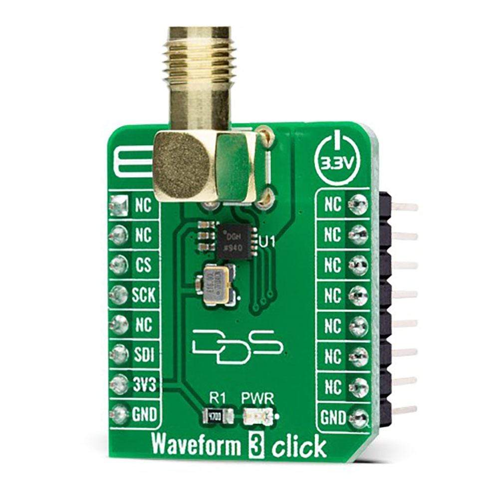
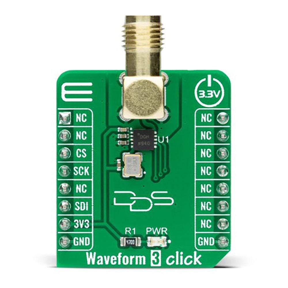
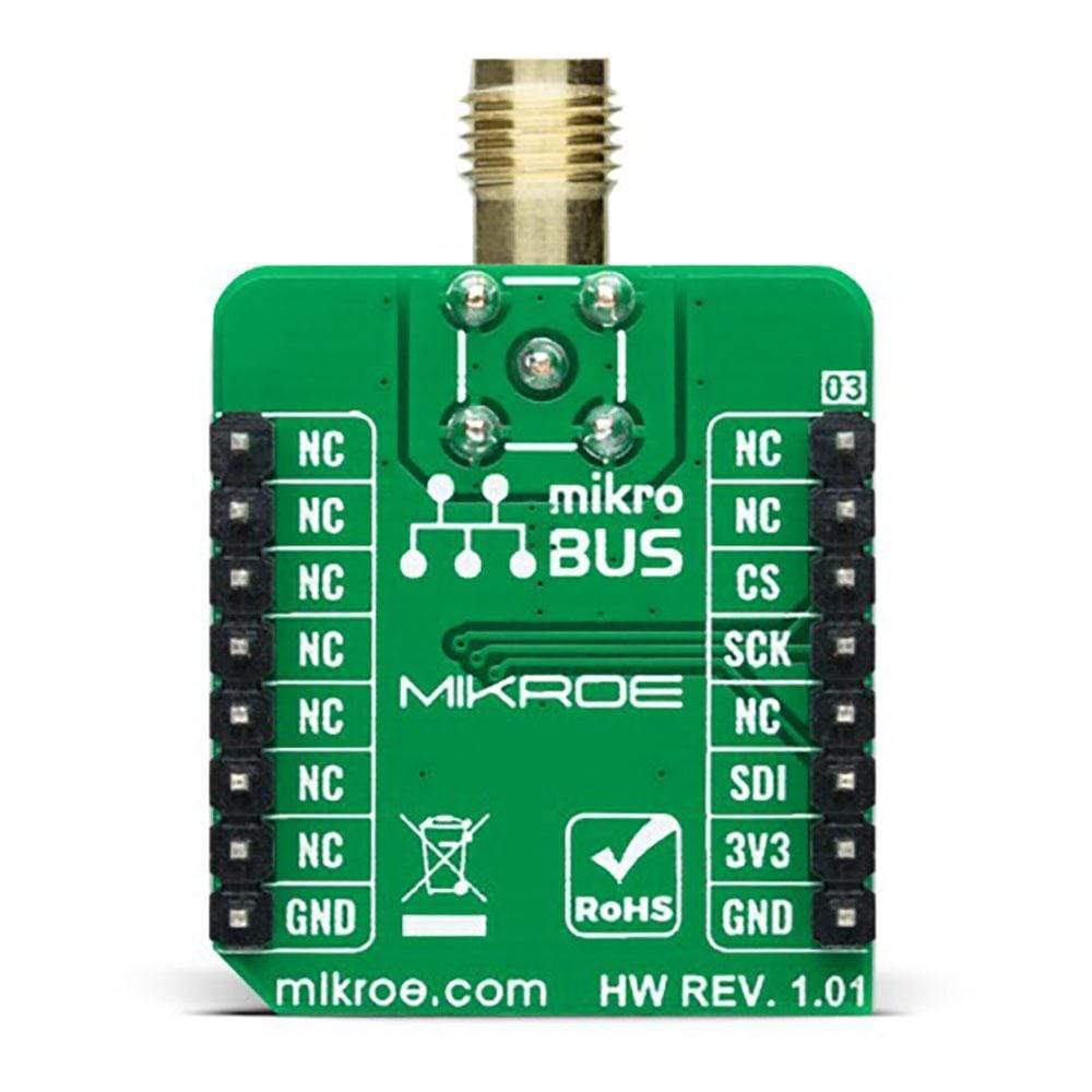
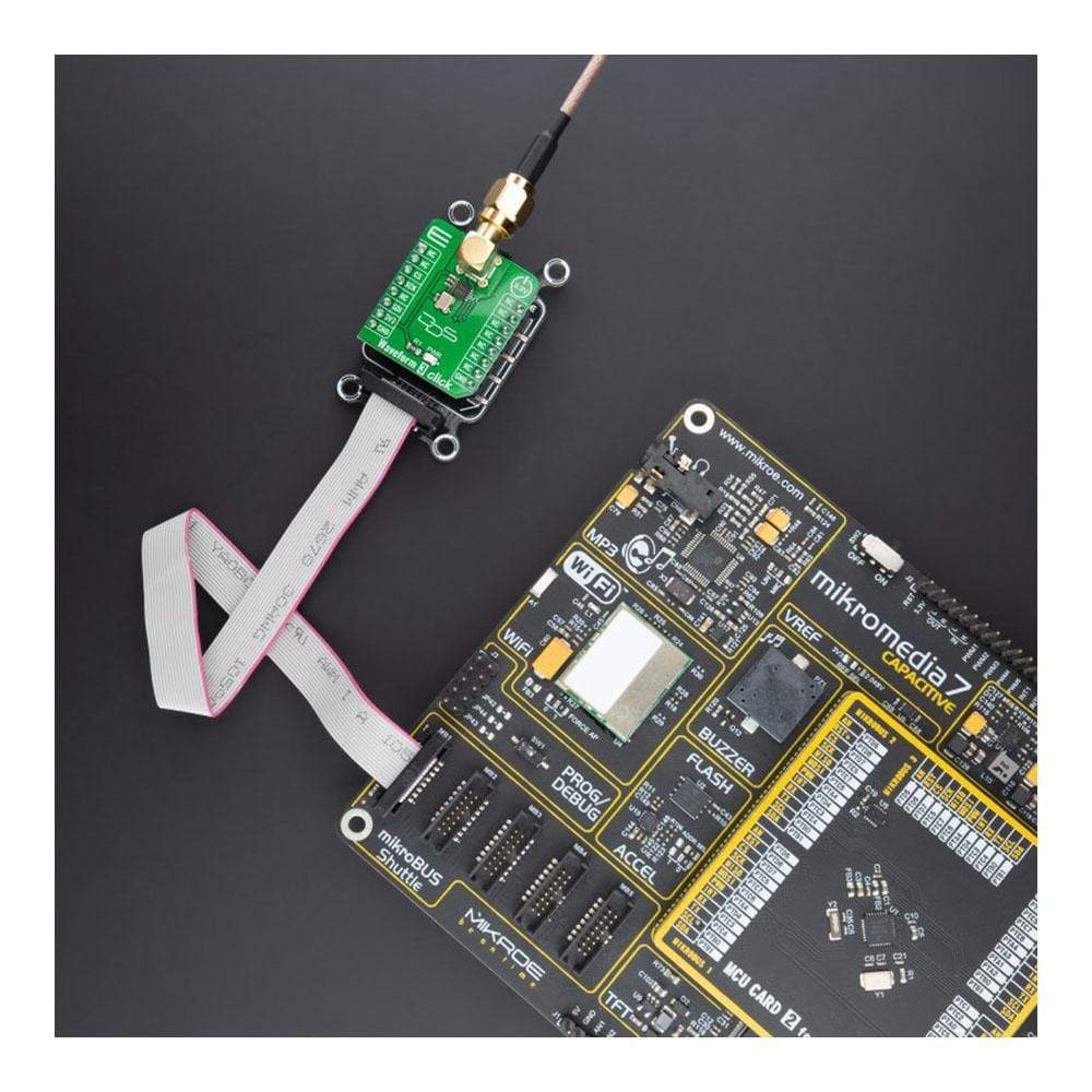
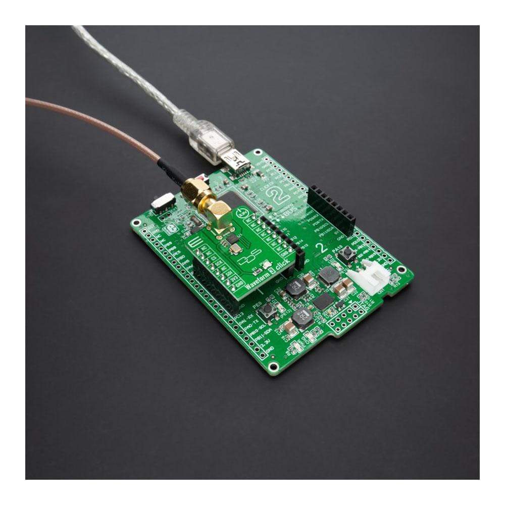
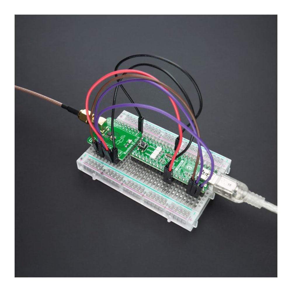
Waveform 3 Click-Platine
Overview
Der Waveform 3 Click Board™ ist eine kompakte Zusatzplatine, die einen Hochleistungssignalgenerator darstellt. Diese Platine verfügt über den AD9837, einen programmierbaren Wellenformgenerator mit geringem Stromverbrauch, der Sinus-, Dreieck- und Rechteckwellenausgänge von Analog Devices erzeugen kann. Dieser direkte digitale Synthesizer erzeugt beliebige analoge Wellenformen aus einem Referenztakt mit fester Frequenz. Er verfügt über eine softwareprogrammierbare Ausgangsfrequenz und -phase über eine 3-adrige SPI-Seriellschnittstelle und ist mit DSP-Standards kompatibel. Dieses Click Board™ eignet sich für die Wellenformerzeugung, die in verschiedenen Sensor-, Betätigungs- und Zeitbereichsreflektometrie-Anwendungen (TDR) erforderlich ist.
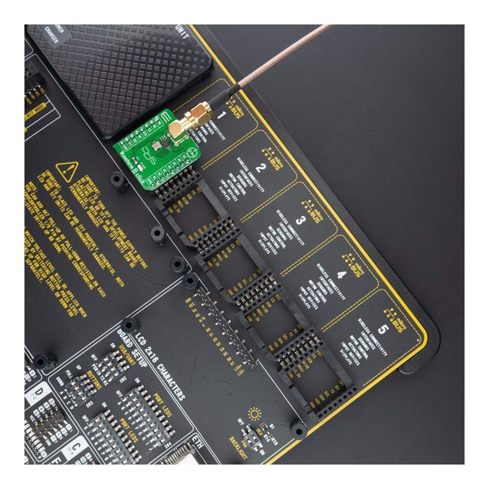
Das Waveform 3 Click Board™ wird durch eine mikroSDK-kompatible Bibliothek unterstützt, die Funktionen enthält, die die Softwareentwicklung vereinfachen. Dieses Click Board™ wird als vollständig getestetes Produkt geliefert und ist bereit für den Einsatz auf einem System, das mit der mikroBUS™-Buchse ausgestattet ist.
How Does The Waveform 3 Click Board™ Work?
The Waveform 3 Click Board™ is based on the AD9837, a fully integrated direct digital synthesis (DDS) device capable of producing high-performance sine and triangular wave outputs from Analog Devices. It also has an internal comparator that allows the creation of a square wave for clock generation. With 28-bits wide frequency registers, the output frequency and phase are software programmable allowing easy tuning. The AD9837 is fully capable of a broad range of complex and straightforward modulation schemes fully implemented in the digital domain, allowing the accurate and precise realization of complex modulation algorithms using DSP techniques.
The internal circuitry of the AD9837 consists of a numerically controlled oscillator (NCO), frequency and phase modulators, SIN ROM, a DAC, a comparator, and a regulator. Also, it has a high-performance, onboard 16MHz trimmed general oscillator that can serve as the master clock for the AD9837 achieving a resolution of 0.06Hz.
The AD9837 offers a variety of outputs available from an onboard output SMA connector. The various output options (sine, triangular, and square wave) available from the AD9837 make this Click board™ suitable for a wide variety of applications, including modulation applications. It is also ideal for signal generator applications, and with its low current consumption, it is also suitable for applications in which it can serve as a local oscillator.
The Waveform 3 Click Board™ communicates with MCU using the 3-Wire SPI serial interface compatible with standard SPI, QSPI™, MICROWIRE™, and DSP interface standards, and operates at clock rates up to 40MHz. Besides, it possesses additional functionality such as a programmable Sleep function that allows external control of the Power-Down mode and Reset function, which resets the appropriate internal registers to 0 to provide an analogue output of mid-scale. It is essential to remind that the reset function does not reset the phase, frequency, or control registers.
The Waveform 3 Click Board™ can be operated only with a 3.3V logic voltage level. The board must perform appropriate logic voltage level conversion before use with MCUs with different logic levels. However, the Click board™ comes equipped with a library containing functions and an example code that can be used, as a reference, for further development.
SPECIFICATIONS
Type | Measurements |
Applications | Can be used for waveform generation required in various sensing, actuation, and time domain reflectometry (TDR) applications. |
On-board modules | AD9837 - low-power programmable waveform generator capable of producing sine, triangular, and square wave outputs from Analog Devices |
Key Features | Low power consumption, high precission, digitally programmable frequency and phase, sinusoidal, triangular, and square wave outputs, power-down option, and more. |
Interface | SPI |
Compatibility | mikroBUS |
Click board size | S (28.6 x 25.4 mm) |
Input Voltage | 3.3V |
PINOUT DIAGRAM
This table shows how the pinout of the Waveform 3 Click Board™ corresponds to the pinout on the mikroBUS™ socket (the latter shown in the two middle columns).
Notes | Pin | Pin | Notes | ||||
---|---|---|---|---|---|---|---|
NC | 1 | AN | PWM | 16 | NC | ||
NC | 2 | RST | INT | 15 | NC | ||
SPI Chip Select | CS | 3 | CS | RX | 14 | NC | |
SPI Clock | SCK | 4 | SCK | TX | 13 | NC | |
NC | 5 | MISO | SCL | 12 | NC | ||
SPI Data IN | SDI | 6 | MOSI | SDA | 11 | NC | |
Power Supply | 3.3V | 7 | 3.3V | 5V | 10 | NC | |
Ground | GND | 8 | GND | GND | 9 | GND | Ground |
ONBOARD SETTINGS AND INDICATORS
Label | Name | Default | Description |
---|---|---|---|
LD1 | PWR | - | Power LED Indicator |
WAVEFORM 3 CLICK ELECTRICAL SPECIFICATIONS
Description | Min | Typ | Max | Unit |
---|---|---|---|---|
Supply Voltage | - | 3.3 | - | V |
Maximum Output Voltage | - | 0.645 | - | V |
Master fclk | - | 16 | - | MHz |
Signal-to-Noise Ratio (SNR) | - | -64 | - | dB |
Resolution | - | 10 | - | bits |
Operating Temperature Range | -40 | +25 | +125 | °C |
How Does The Waveform 3 Click Board™ Work?
The Waveform 3 Click Board™ is based on the AD9837, a fully integrated direct digital synthesis (DDS) device capable of producing high-performance sine and triangular wave outputs from Analog Devices. It also has an internal comparator that allows the creation of a square wave for clock generation. With 28-bits wide frequency registers, the output frequency and phase are software programmable allowing easy tuning. The AD9837 is fully capable of a broad range of complex and straightforward modulation schemes fully implemented in the digital domain, allowing the accurate and precise realization of complex modulation algorithms using DSP techniques.
The internal circuitry of the AD9837 consists of a numerically controlled oscillator (NCO), frequency and phase modulators, SIN ROM, a DAC, a comparator, and a regulator. Also, it has a high-performance, onboard 16MHz trimmed general oscillator that can serve as the master clock for the AD9837 achieving a resolution of 0.06Hz.
The AD9837 offers a variety of outputs available from an onboard output SMA connector. The various output options (sine, triangular, and square wave) available from the AD9837 make this Click board™ suitable for a wide variety of applications, including modulation applications. It is also ideal for signal generator applications, and with its low current consumption, it is also suitable for applications in which it can serve as a local oscillator.
The Waveform 3 Click Board™ communicates with MCU using the 3-Wire SPI serial interface compatible with standard SPI, QSPI™, MICROWIRE™, and DSP interface standards, and operates at clock rates up to 40MHz. Besides, it possesses additional functionality such as a programmable Sleep function that allows external control of the Power-Down mode and Reset function, which resets the appropriate internal registers to 0 to provide an analogue output of mid-scale. It is essential to remind that the reset function does not reset the phase, frequency, or control registers.
The Waveform 3 Click Board™ can be operated only with a 3.3V logic voltage level. The board must perform appropriate logic voltage level conversion before use with MCUs with different logic levels. However, the Click board™ comes equipped with a library containing functions and an example code that can be used, as a reference, for further development.
SPECIFICATIONS
Type | Measurements |
Applications | Can be used for waveform generation required in various sensing, actuation, and time domain reflectometry (TDR) applications. |
On-board modules | AD9837 - low-power programmable waveform generator capable of producing sine, triangular, and square wave outputs from Analog Devices |
Key Features | Low power consumption, high precision, digitally programmable frequency and phase, sinusoidal, triangular, and square wave outputs, power-down option, and more. |
Interface | SPI |
Compatibility | mikroBUS |
Click board size | S (28.6 x 25.4 mm) |
Input Voltage | 3.3V |
PINOUT DIAGRAM
This table shows how the pinout of the Waveform 3 Click Board™ corresponds to the pinout on the mikroBUS™ socket (the latter shown in the two middle columns).
Notes | Pin | Pin | Notes | ||||
---|---|---|---|---|---|---|---|
NC | 1 | AN | PWM | 16 | NC | ||
NC | 2 | RST | INT | 15 | NC | ||
SPI Chip Select | CS | 3 | CS | RX | 14 | NC | |
SPI Clock | SCK | 4 | SCK | TX | 13 | NC | |
NC | 5 | MISO | SCL | 12 | NC | ||
SPI Data IN | SDI | 6 | MOSI | SDA | 11 | NC | |
Power Supply | 3.3V | 7 | 3.3V | 5V | 10 | NC | |
Ground | GND | 8 | GND | GND | 9 | GND | Ground |
ONBOARD SETTINGS AND INDICATORS
Label | Name | Default | Description |
---|---|---|---|
LD1 | PWR | - | Power LED Indicator |
WAVEFORM 3 CLICK ELECTRICAL SPECIFICATIONS
Description | Min | Typ | Max | Unit |
---|---|---|---|---|
Supply Voltage | - | 3.3 | - | V |
Maximum Output Voltage | - | 0.645 | - | V |
Master fclk | - | 16 | - | MHz |
Signal-to-Noise Ratio (SNR) | - | -64 | - | dB |
Resolution | - | 10 | - | bits |
Operating Temperature Range | -40 | +25 | +125 | °C |
Software Support
We provide a library for the Waveform 3 Click Board™ as well as a demo application (example), developed using MikroElektronika compilers. The demo can run on all the main MikroElektronika development boards.
The package can be downloaded/installed directly from NECTO Studio The package Manager (recommended), downloaded from our LibStock™ or found on the mikroE Github account.
Library Description
This library contains API for the Waveform 3 Click Board™ driver.
Key Functions
waveform3_cfg_setup
- Config Object Initialization function.waveform3_init
- Initialization function.waveform3_default_cfg
- Click Default Configuration function.
Example Description
This demo app shows the basic capabilities of the Waveform 3 Click Board™. First, the sinusoidal wave is incremented to the targeted frequency for a visually pleasing introduction after which it changes between 4 modes of output.
The demo application is composed of two sections :
void application_task ( void ) { uint8_t cfg_mode_switch; if ( start_frequency < target_frequency ) { if ( start_frequency / rising_factor < 100 ) { start_frequency += rising_factor; waveform3_set_freq( &waveform3, start_frequency, WAVEFORM3_CFG_FREQ_REG0 ); Delay_ms( 5 ); } else { rising_factor += 10; } } else { for ( cfg_mode_switch = 0 ; cfg_mode_switch < 4 ; cfg_mode_switch++ ) { waveform3_set_mode( &waveform3, cfg_mode_switch, WAVEFORM3_CFG_FREQ_REG0, WAVEFORM3_CFG_PHASE_REG0 ); Delay_ms( 5000 ); } } }
The full application code, and ready-to-use projects can be installed directly from NECTO Studio The package Manager (recommended), downloaded from our LibStock™ or found on the mikroE Github account.
Other mikroE Libraries used in the example:
- MikroSDK.Board
- MikroSDK.Log
- Click.Waveform3
Additional Notes and Information
Depending on the development board you are using, you may need USB UART Click Board™, USB UART 2 Click Board™ or RS232 Click Board™ to connect to your PC, for development systems with no UART to USB interface available on the board. The terminal available in all MikroElektronika compilers, or any other terminal application of your choice, can be used to read the message.
MIKROSDK
The Waveform 3 Click Board™ is supported with mikroSDK - MikroElektronika Software Development Kit. To ensure proper operation of mikroSDK compliant Click board™ demo applications, mikroSDK should be downloaded from the LibStock and installed for the compiler you are using.
Frequently Asked Questions
Have a Question?
Be the first to ask a question about this.