Druck 14 Click Board
Overview
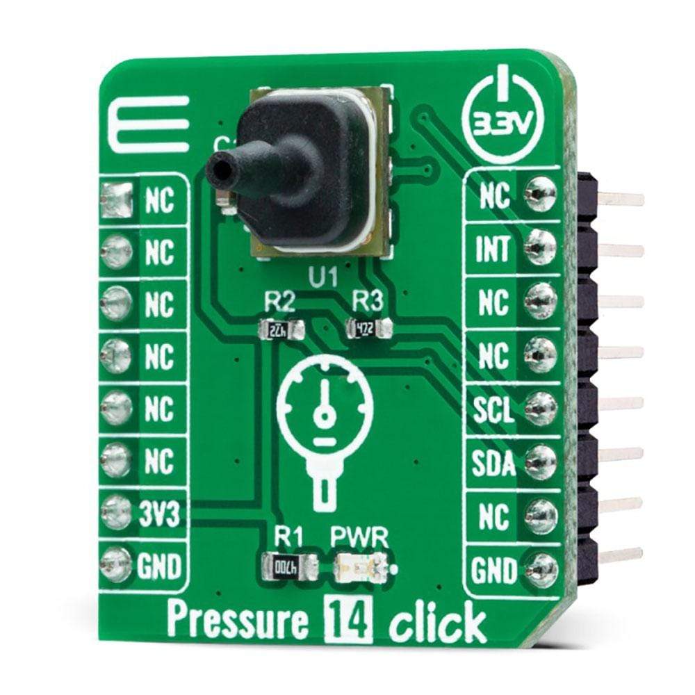
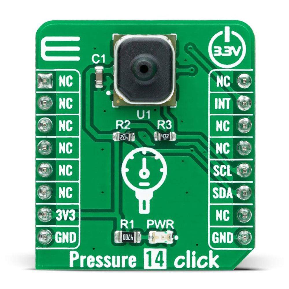
Der Pressure 14 Click Board™ ist eine kompakte Zusatzplatine, die einen Drucksensor zur Platinenmontage enthält. Diese Platine verfügt über den ABP2LANT060PG2A3XX, einen piezoresistiven Silizium-Drucksensor mit einem digitalen Ausgang zum Ablesen des Drucks über den angegebenen vollen Druckbereich und einen Temperaturbereich von Honeywell Sensing and Productivity Solutions. Dieser I2C-konfigurierbare Sensor ist kalibriert und temperaturkompensiert für Sensorversatz, Empfindlichkeit, Temperatureffekte und Genauigkeitsfehler, einschließlich Nichtlinearität, Wiederholbarkeit und Hysterese, unter Verwendung eines integrierten ASIC. Dieses Click Board™ ist für Druckmessungen in Automobilanwendungen, Industrie- und Verbraucheranwendungen geeignet.
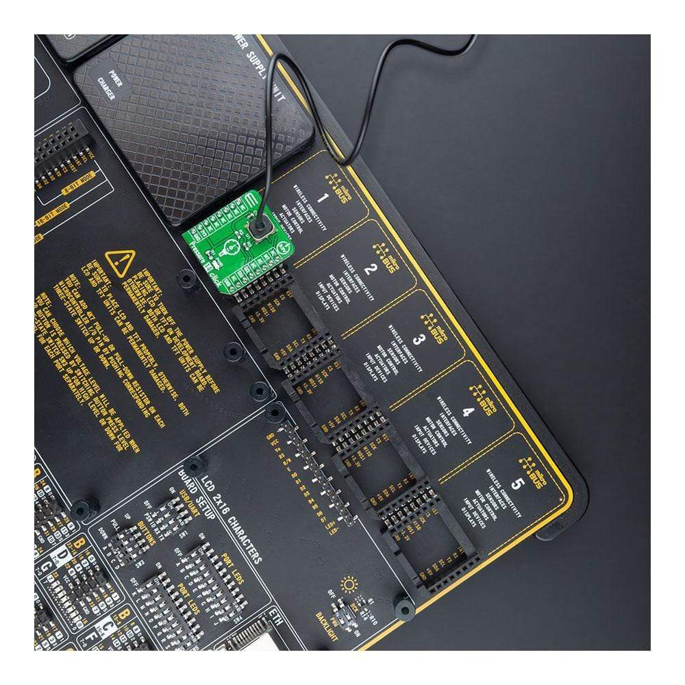
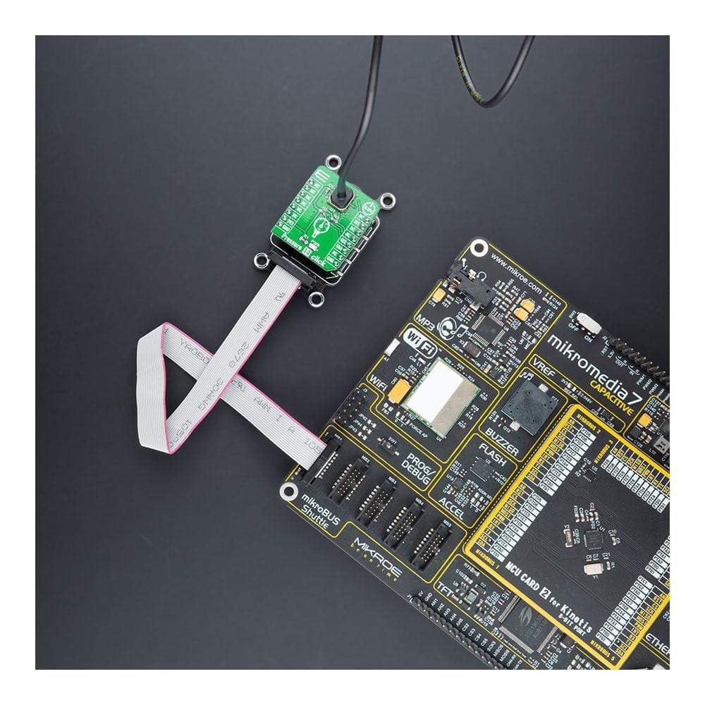
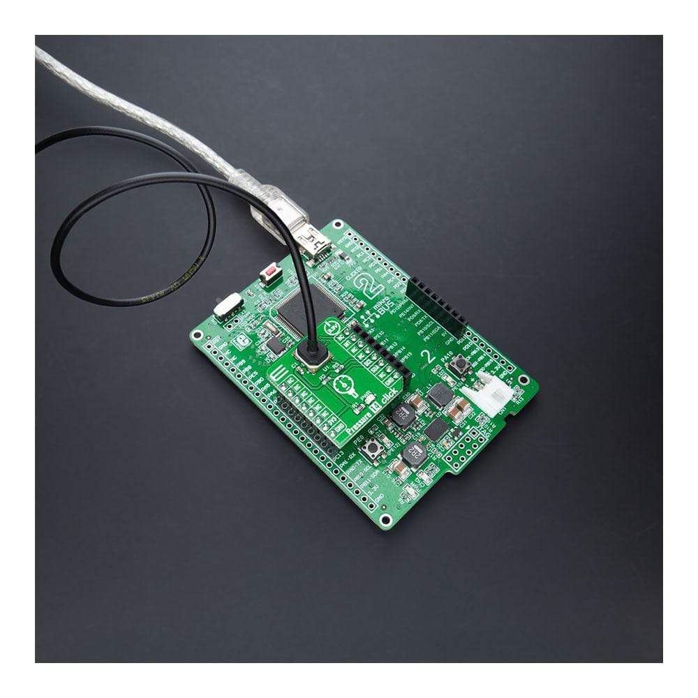
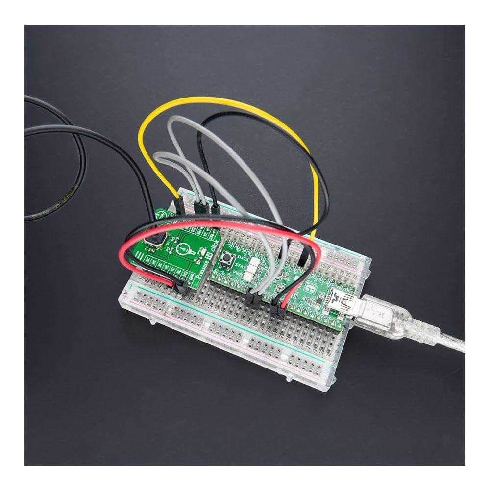
Das Pressure 14 Click Board™ wird durch eine mikroSDK-kompatible Bibliothek unterstützt, die Funktionen enthält, die die Softwareentwicklung vereinfachen. Dieses Click Board™ wird als vollständig getestetes Produkt geliefert und ist bereit für den Einsatz auf einem System, das mit der mikroBUS™-Buchse ausgestattet ist.
How Does the Pressure 14 Click Board™ Work?
The Pressure 14 Click Board™ is based on the ABP2LANT060PG2A3XX, a piezoresistive silicon pressure sensor offering a digital output for reading pressure over the specified full-scale pressure span from Honeywell Sensing and Productivity Solutions. Its characterized by long-term stability and accuracy, ultra-low power consumption, a wide pressure range from 0 to 60 psi, and its compatibility with plenty of liquid media. Also, it is a perfect choice for pressure measurements in automotive applications, industrial and consumer applications.
The ABP2LANT060PG2A3XX defines an I2C configurable ABP2 Series Amplified Basic pressure sensor calibrated and temperature compensated for sensor offset, sensitivity, temperature effects, and accuracy errors. ABP2 series represents flexible and versatile sensors at which the calibrated output values for pressure and temperature update at approximately 200 Hz. The liquid media option includes an additional silicone-based gel coating to protect the electronics under pressure port, enabling usage with non-corrosive liquids (e.g., water and saline) and in applications where condensation can occur.
The Pressure 14 Click Board™ communicates with MCU using the standard I2C 2-Wire interface and supports both Standard and Fast Mode with a transfer rate of 100 and 400kbit/s. Following the address and read bit from the MCU, the ABP2 Series digital pressure sensors can output up to 7 bytes of data, using a default I2C address of 40 (28h). Also, it uses an additional pin, the INT pin of the mikroBUS™ socket, used as an 'end-of-conversion' indicator. This pin sets HIGH when measurement and calculation have been completed, and then the data is ready to be clocked out.
The Pressure 14 Click Board™ is designed to be operated only with a 3.3V logic voltage level. A proper logic voltage level conversion should be performed before the Click board™ is used with MCUs with different logic levels. However, the Click board™ comes equipped with a library that contains functions and an example code that can be used, as a reference, for further development.
SPECIFICATIONS
Type | Pressure |
Applications | Can be used for pressure measurements in automotive applications, industrial and consumer applications. |
On-board modules | ABP2LANT060PG2A3XX - piezoresistive silicon pressure sensor offering a digital output for reading pressure over the specified full-scale pressure span from Honeywell Sensing and Productivity Solutions. |
Key Features | Ultra-low power consumption, calibrated and temperature compensated/amplified for sensor offset, sensitivity, temperature effects, high accuracy, liquid media capability, and more. |
Interface | I2C |
Compatibility | mikroBUS |
Click board size | S (28.6 x 25.4 mm) |
Input Voltage | 3.3V |
PINOUT DIAGRAM
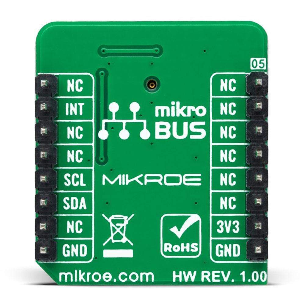
This table shows how the pinout on the Pressure 14 Click Board™ corresponds to the pinout on the mikroBUS™ socket (the latter shown in the two middle columns).
Notes | Pin | Pin | Notes | ||||
---|---|---|---|---|---|---|---|
NC | 1 | AN | PWM | 16 | NC | ||
NC | 2 | RST | INT | 15 | INT | Interrupt | |
NC | 3 | CS | RX | 14 | NC | ||
NC | 4 | SCK | TX | 13 | NC | ||
NC | 5 | MISO | SCL | 12 | SCL | I2C Clock | |
NC | 6 | MOSI | SDA | 11 | SDA | I2C Data | |
Power Supply | 3.3V | 7 | 3.3V | 5V | 10 | NC | |
Ground | GND | 8 | GND | GND | 9 | GND | Ground |
ONBOARD SETTINGS AND INDICATORS
Label | Name | Default | Description |
---|---|---|---|
LD1 | PWR | - | Power LED Indicator |
PRESSURE 14 CLICK ELECTRICAL SPECIFICATIONS
Description | Min | Typ | Max | Unit |
---|---|---|---|---|
Supply Voltage | - | 3.3 | - | V |
Pressure Measurement Range | 0 | - | 60 | psi |
Accuracy | - | - | ±0.25 | %FSS BFSL |
Resolution | 14 | - | - | bits |
Operating Temperature Range | -40 | +25 | +110 | °C |
Software Support
We provide a library for the Pressure 14 Click Board™ on our LibStock page, as well as a demo application (example), developed using MikroElektronika compilers. The demo can run on all the main MikroElektronika development boards.
Library Description
The library covers all the necessary functions to control the Pressure 14 Click Board™. The library performs a standard I2C interface communication.
Key Functions
void pressure14_measure_cmd ( void )
- Output Measurement Command function.void pressure14_read_press_and_temp ( uint8_t *status_byte, uint32_t *pressure_data, uint32_t *temp_data );
- Read pressure and temperature function.float pressure14_get_pressure ( uint32_t pressure_raw, uint8_t conv_unit )
- Calculate pressure function.
Example Description
The application is composed of three sections :
- System Initialization - Initializes I2C and UART LOG and sets INT pin as input.
- Application Initialization - The initialization driver enables I2C.
- Application Task - This is an example that demonstrates the use of the Pressure 14 Click board™. In this example, the output measurement command is sent first forcing the ABP2 pressure sensor to exit standby mode and enter operating mode. The device busy state is evaluated via the end-of-conversion pin ( INT ) following the pressure and temperature data acquisition and calculation. The results are being sent to the Usart Terminal. This task repeats every 5 sec.
void application_task ( ) { pressure14_measure_cmd( ); Delay_ms( 10 ); if ( pressure14_check_busy_flag_int( ) == device_busy_false ) { pressure14_read_press_and_temp( &status, &pressure_tmp, &temperature_tmp ); Delay_ms( 100 ); pressure = pressure14_get_pressure( pressure_tmp, PRESSURE14_CONV_UNIT_MILIBAR ); temperature = pressure14_get_temperature( temperature_tmp, PRESSURE14_CONV_UNIT_CELSIUS ); mikrobus_logWrite( " Pressure : ", _LOG_TEXT ); FloatToStr( pressure, demo_txt ); mikrobus_logWrite( demo_txt, _LOG_TEXT ); mikrobus_logWrite( " mbar", _LOG_LINE ); mikrobus_logWrite( " Temperature : ", _LOG_TEXT ); FloatToStr( temperature, demo_txt ); mikrobus_logWrite( demo_txt, _LOG_TEXT ); mikrobus_logWrite( " C", _LOG_LINE ); mikrobus_logWrite( "-----------------------", _LOG_LINE ); } Delay_ms( 2000 ); }
The full application code, and ready to use projects can be found on our LibStock page.
Other mikroE Libraries used in the example:
- I2C
- UART
Additional Notes and Information
Depending on the development board you are using, you may need a USB UART click, USB UART 2 click or RS232 click to connect to your PC, for development systems with no UART to USB interface available on the board. The terminal available in all MikroElektronika compilers, or any other terminal application of your choice, can be used to read the message.
MIKROSDK
The Pressure 14 Click Board™ is supported with mikroSDK - MikroElektronika Software Development Kit. To ensure proper operation of mikroSDK compliant Click board™ demo applications, mikroSDK should be downloaded from the LibStock and installed for the compiler you are using.
Frequently Asked Questions
Have a Question?
Be the first to ask a question about this.