


Mikroelektronika d.o.o.
RTD 2 Click-Platine
RTD 2 Click-Platine
SKU: MIKROE-4282
Verfügbarkeit für Abholungen konnte nicht geladen werden


Overview
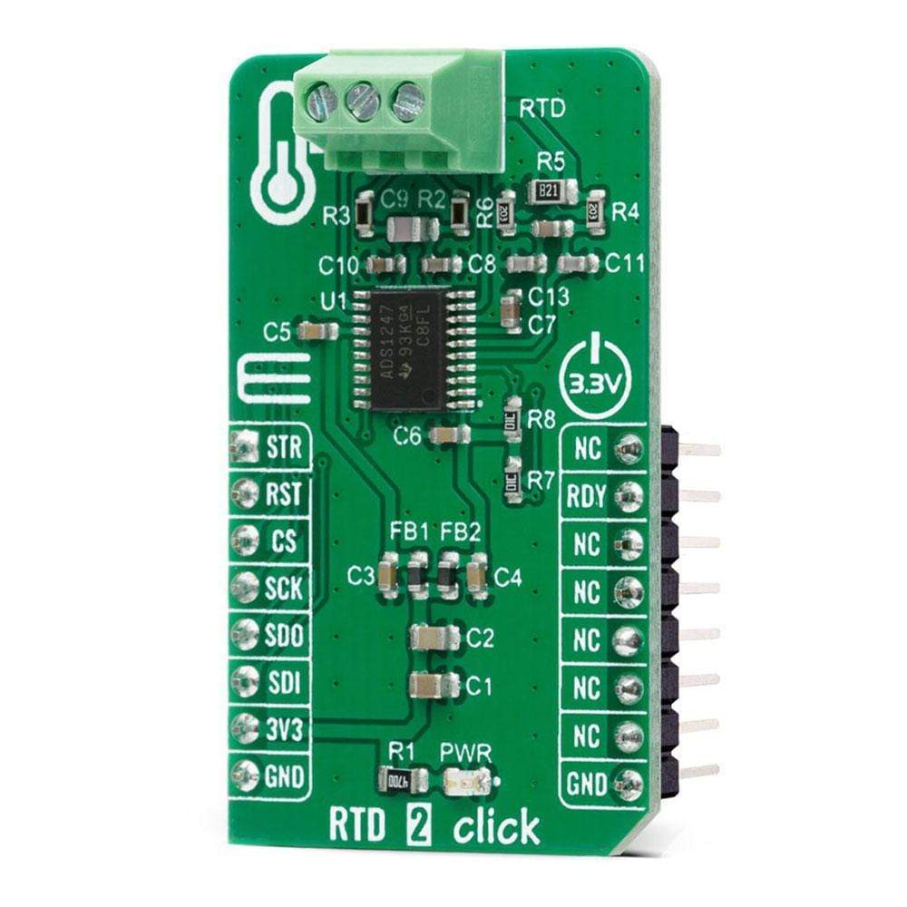
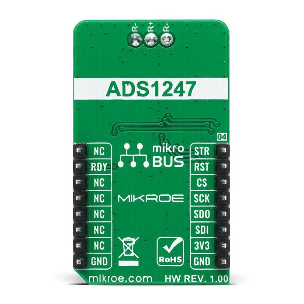
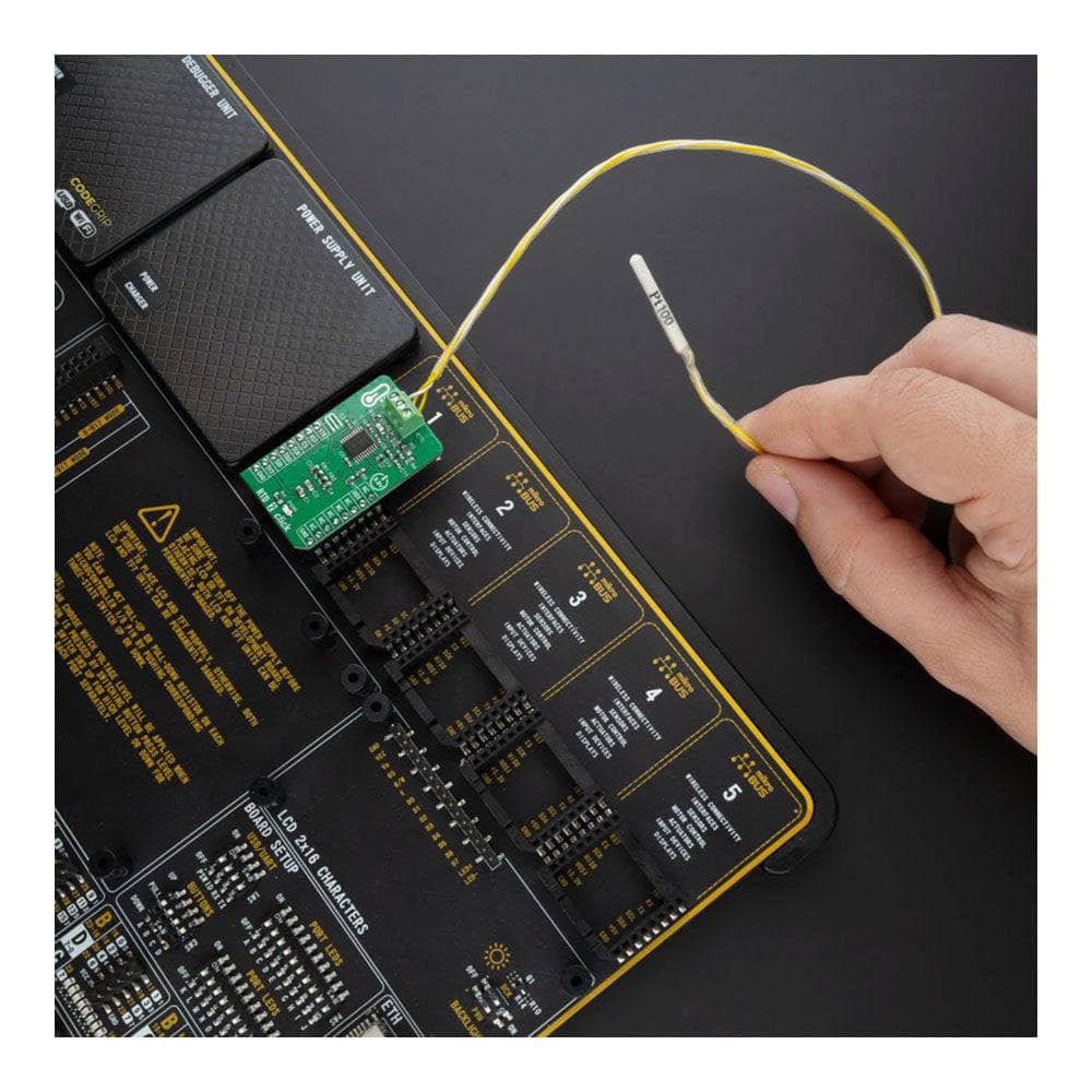
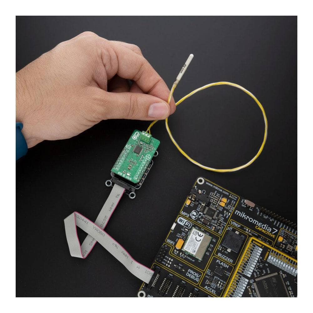
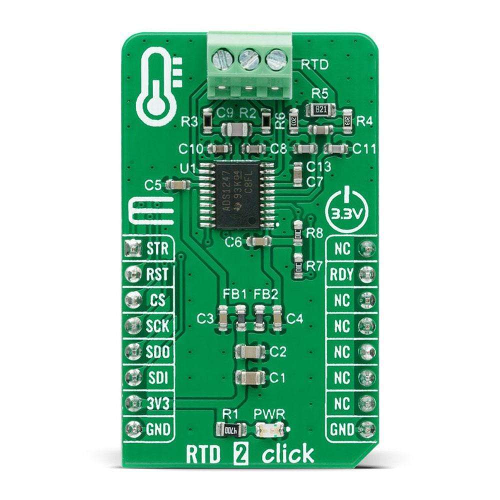
The RTD 2 Click Board™ is a compact add-on board used for applications with resistive elements that change resistance over temperature. This board features the ADS1247, 24-bit analogue-to-digital converter with a programmable gain amplifier (PGA) for sensor measurement applications from Texas Instruments. It features a precision delta-sigma (ΔΣ) ADC with a single-cycle settling digital filter, and an internal oscillator, but also provides a low-drift voltage reference, and two matched programmable excitation current sources (IDACs). It also integrates sensor burn-out detection, voltage bias for thermocouples, system monitoring, and digital GPIOs. This Click Board™ is suitable for temperature sensor measurements such as RTDs, thermocouples and thermistors, for pressure measurements, process control, and many more.
The RTD 2 Click Board™ is supported by a mikroSDK compliant library, which includes functions that simplify software development. This Click Board™ comes as a fully tested product, ready to be used on a system equipped with the mikroBUS™ socket
Downloads
Das RTD 2 Click Board™ ist eine kompakte Zusatzplatine für Anwendungen mit Widerstandselementen, die ihren Widerstand über die Temperatur ändern. Diese Platine verfügt über den 24-Bit-Analog-Digital-Wandler ADS1247 mit einem programmierbaren Verstärkungsverstärker (PGA) für Sensormessanwendungen von Texas Instruments. Es verfügt über einen präzisen Delta-Sigma-ADC (ΔΣ) mit einem einzyklischen Einschwing-Digitalfilter und einen internen Oszillator, bietet aber auch eine Spannungsreferenz mit geringer Drift und zwei angepasste programmierbare Erregerstromquellen (IDACs). Es integriert außerdem Sensor-Burnout-Erkennung, Spannungsvorspannung für Thermoelemente, Systemüberwachung und digitale GPIOs. Dieses Click Board™ ist für Temperatursensormessungen wie RTDs, Thermoelemente und Thermistoren, für Druckmessungen, Prozesssteuerung und vieles mehr geeignet.
Das RTD 2 Click Board™ wird durch eine mikroSDK-kompatible Bibliothek unterstützt, die Funktionen enthält, die die Softwareentwicklung vereinfachen. Dieses Click Board™ wird als vollständig getestetes Produkt geliefert und ist bereit für den Einsatz auf einem System, das mit der mikroBUS™-Buchse ausgestattet ist
| General Information | |
|---|---|
Part Number (SKU) |
MIKROE-4282
|
Manufacturer |
|
| Physical and Mechanical | |
Weight |
0.019 kg
|
| Other | |
EAN |
8606027380624
|
Frequently Asked Questions
Have a Question?
Be the first to ask a question about this.