


Mikroelektronika d.o.o.
I2C MUX 4 Click-Platine
I2C MUX 4 Click-Platine
SKU: MIKROE-4240
Verfügbarkeit für Abholungen konnte nicht geladen werden


Overview
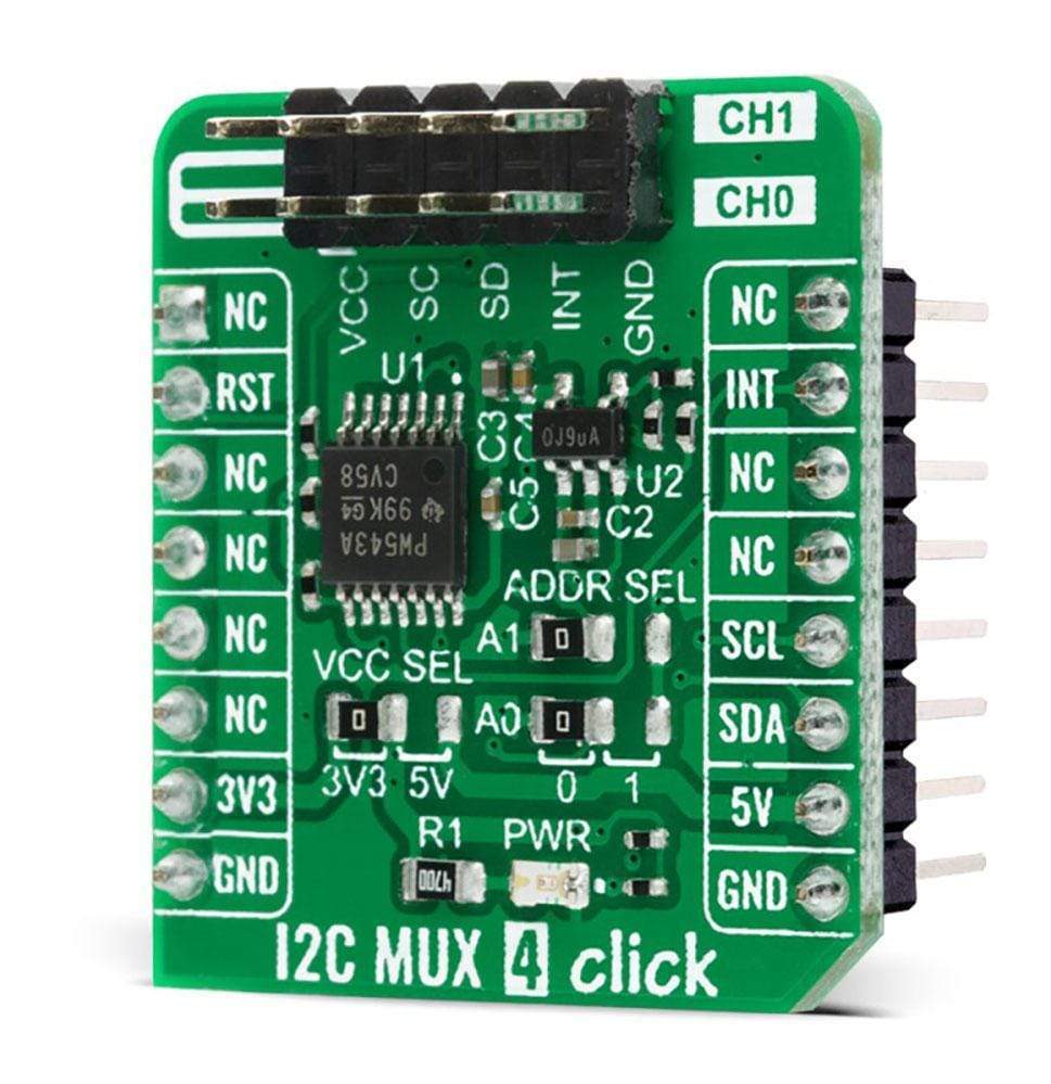
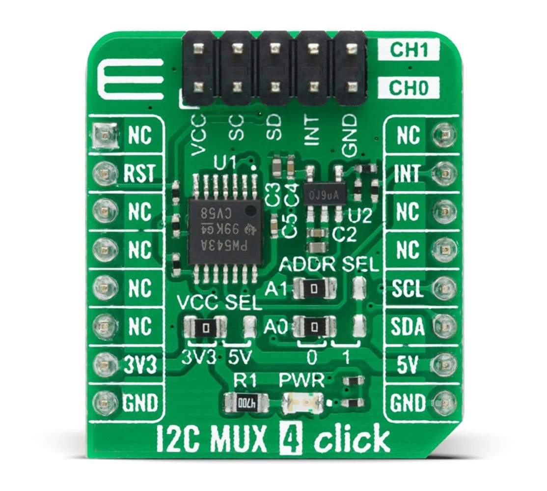
The I2C MUX 4 Click Board™ is a compact add-on board that contains a dual bidirectional translating switch dedicated for applications with I2C slave address conflicts. This board features the TCA9543APWR, a low voltage 2-channel I2C bus switch with interrupt logic from Texas Instruments. The master SCL/SDA signals are directed to two downstream pairs, or channels, where either individual SCL/SDA channel or both channels can be selected by setting the programmable control register. It has two interrupts and a Reset input which allows the TCA9543A to recover from a situation where one of the downstream I2C buses is stuck in a low state. This Click Board™ is suitable to work with I2C interfaces for applications such as fault isolation, address conflict, level translation, or broadcast communication.
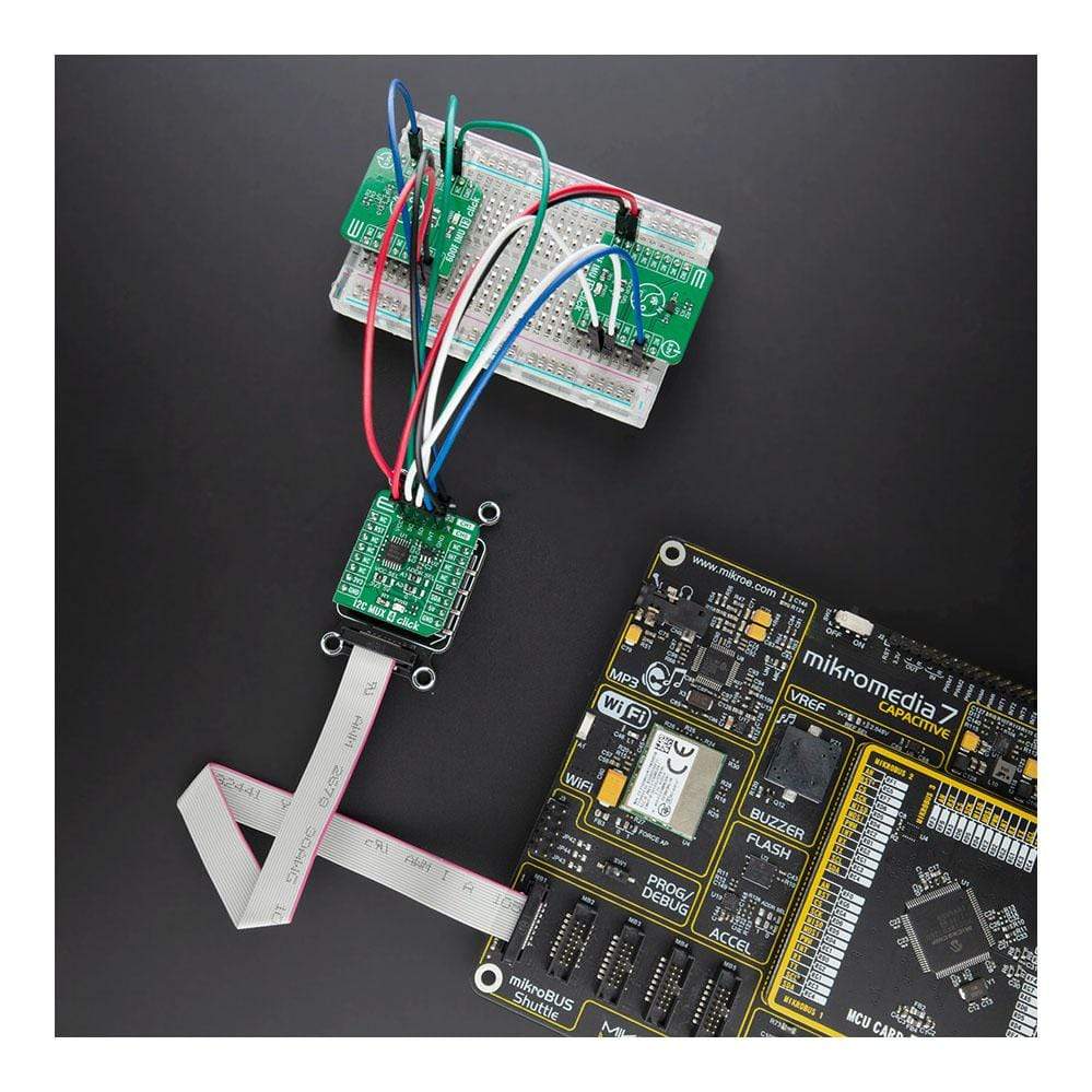
The I2C MUX 4 Click Board™ is supported by a mikroSDK compliant library, which includes functions that simplify software development. This Click Board™ comes as a fully tested product, ready to be used on a system equipped with the mikroBUS™ socket.
Downloads
Der I2C MUX 4 Click Board™ ist eine kompakte Zusatzplatine, die einen dualen bidirektionalen Übersetzungsschalter enthält, der für Anwendungen mit I2C-Slave-Adresskonflikten vorgesehen ist. Diese Platine verfügt über den TCA9543APWR, einen Niederspannungs-2-Kanal-I2C-Busschalter mit Interrupt-Logik von Texas Instruments. Die Master-SCL/SDA-Signale werden an zwei nachgeschaltete Paare oder Kanäle geleitet, wobei entweder ein einzelner SCL/SDA-Kanal oder beide Kanäle durch Einstellen des programmierbaren Steuerregisters ausgewählt werden können. Es verfügt über zwei Interrupts und einen Reset-Eingang, der es dem TCA9543A ermöglicht, sich von einer Situation zu erholen, in der einer der nachgeschalteten I2C-Busse in einem niedrigen Zustand feststeckt. Dieses Click Board™ eignet sich für die Arbeit mit I2C-Schnittstellen für Anwendungen wie Fehlerisolierung, Adresskonflikte, Pegelübersetzung oder Broadcast-Kommunikation.
Das I2C MUX 4 Click Board™ wird von einer mikroSDK-kompatiblen Bibliothek unterstützt, die Funktionen enthält, die die Softwareentwicklung vereinfachen. Dieses Click Board™ wird als vollständig getestetes Produkt geliefert und ist bereit für den Einsatz auf einem System, das mit der mikroBUS™-Buchse ausgestattet ist.
| General Information | |
|---|---|
Part Number (SKU) |
MIKROE-4240
|
Manufacturer |
|
| Physical and Mechanical | |
Weight |
0.017 kg
|
| Other | |
EAN |
8606027380334
|
Frequently Asked Questions
Have a Question?
Be the first to ask a question about this.