6DOF IMU 14 Click-Platine
Overview
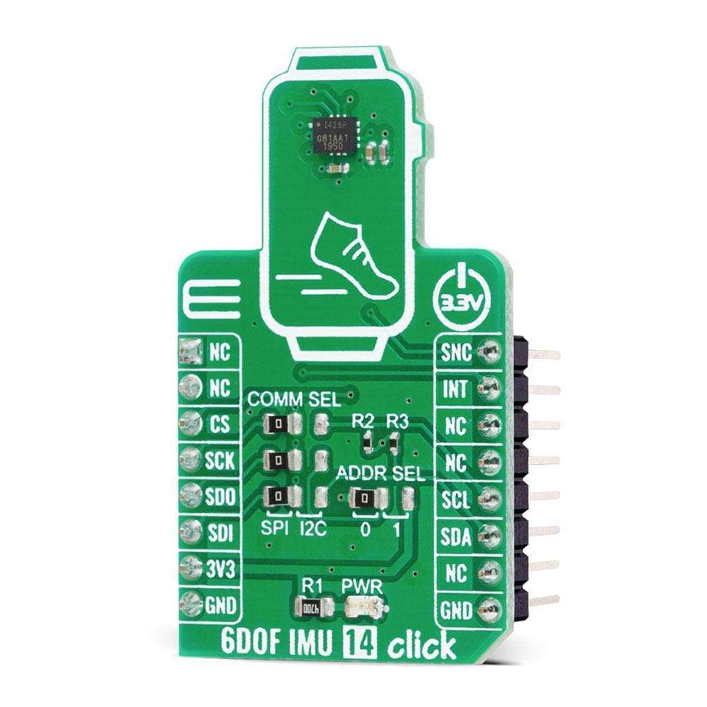
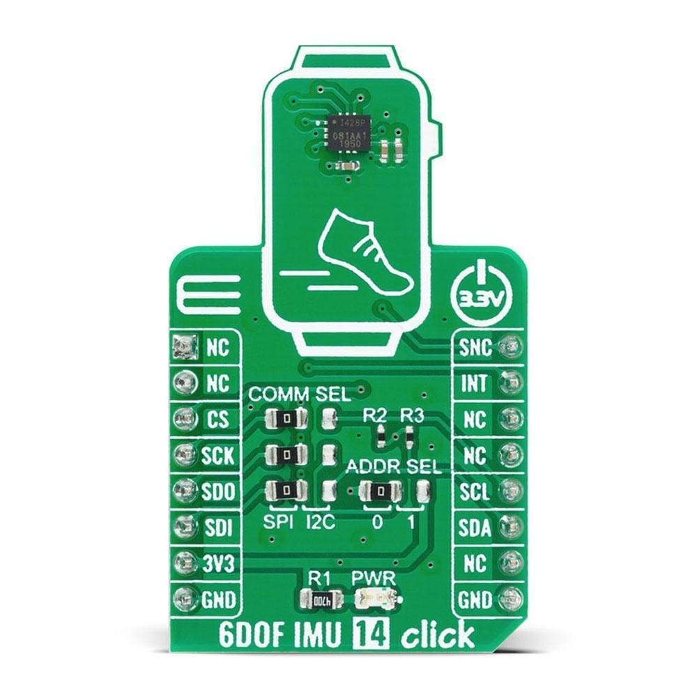
Das 6DOF IMU 14 Click Board™ ist eine kompakte Zusatzplatine, die ein 6-Achsen-MEMS-Bewegungsverfolgungsgerät enthält, das ein 3-Achsen-Gyroskop und einen 3-Achsen-Beschleunigungsmesser kombiniert. Diese Platine verfügt über das hochpräzise 6-Achsen-MEMS-Bewegungsverfolgungsgerät ICM-42688-P von TDK InvenSense. Es verfügt über eine konfigurierbare Hostschnittstelle, die sowohl I2C- als auch SPI-Seriellkommunikation unterstützt, verfügt über ein 2-kB-FIFO und 2 programmierbare Interrupts mit extrem energiesparender Wake-on-Motion-Unterstützung zur Minimierung des Stromverbrauchs des Systems. Dieses Click Board™ ist eine ausgezeichnete Wahl für Anwendungen wie Gestenerkennung, Aktivitätsklassifizierung und Schrittzähler sowie programmierbare digitale Filter und einen eingebetteten Temperatursensor.
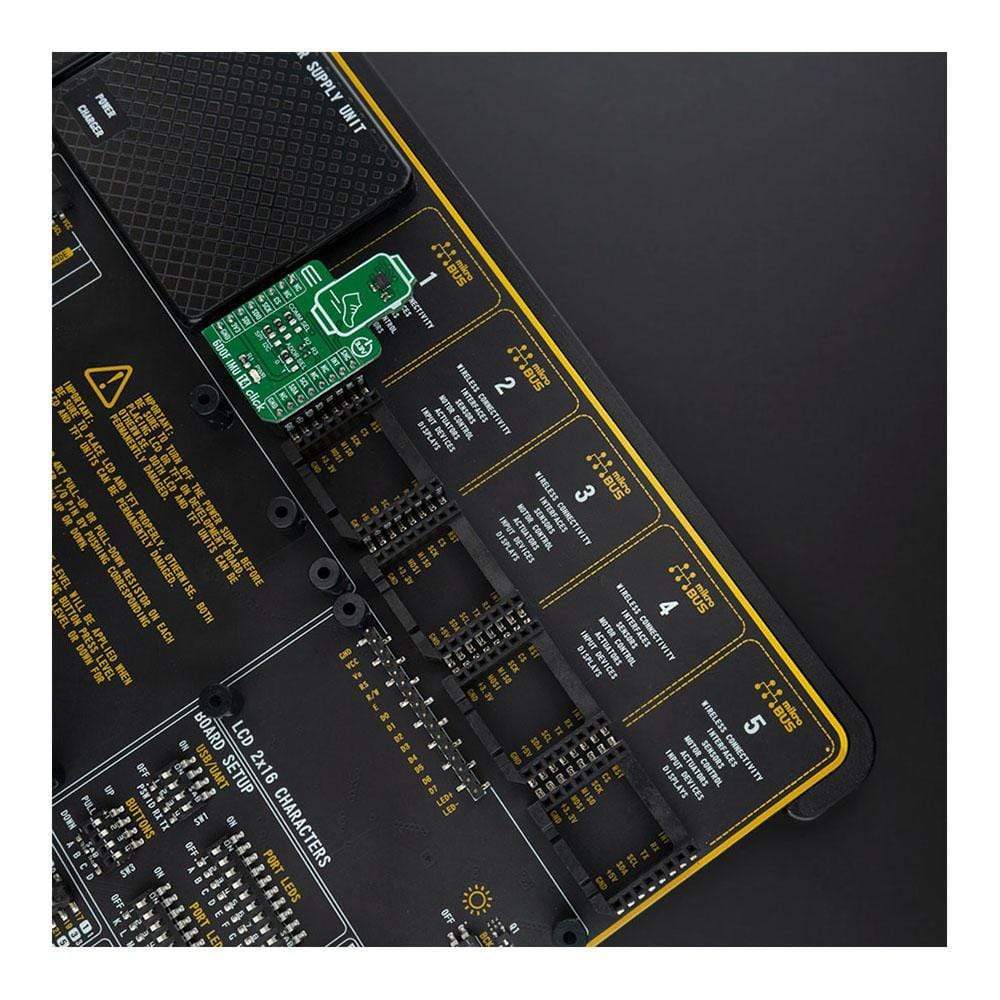
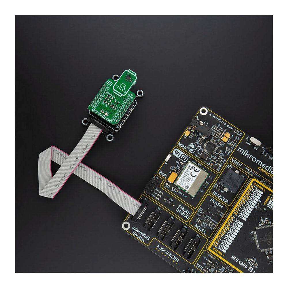
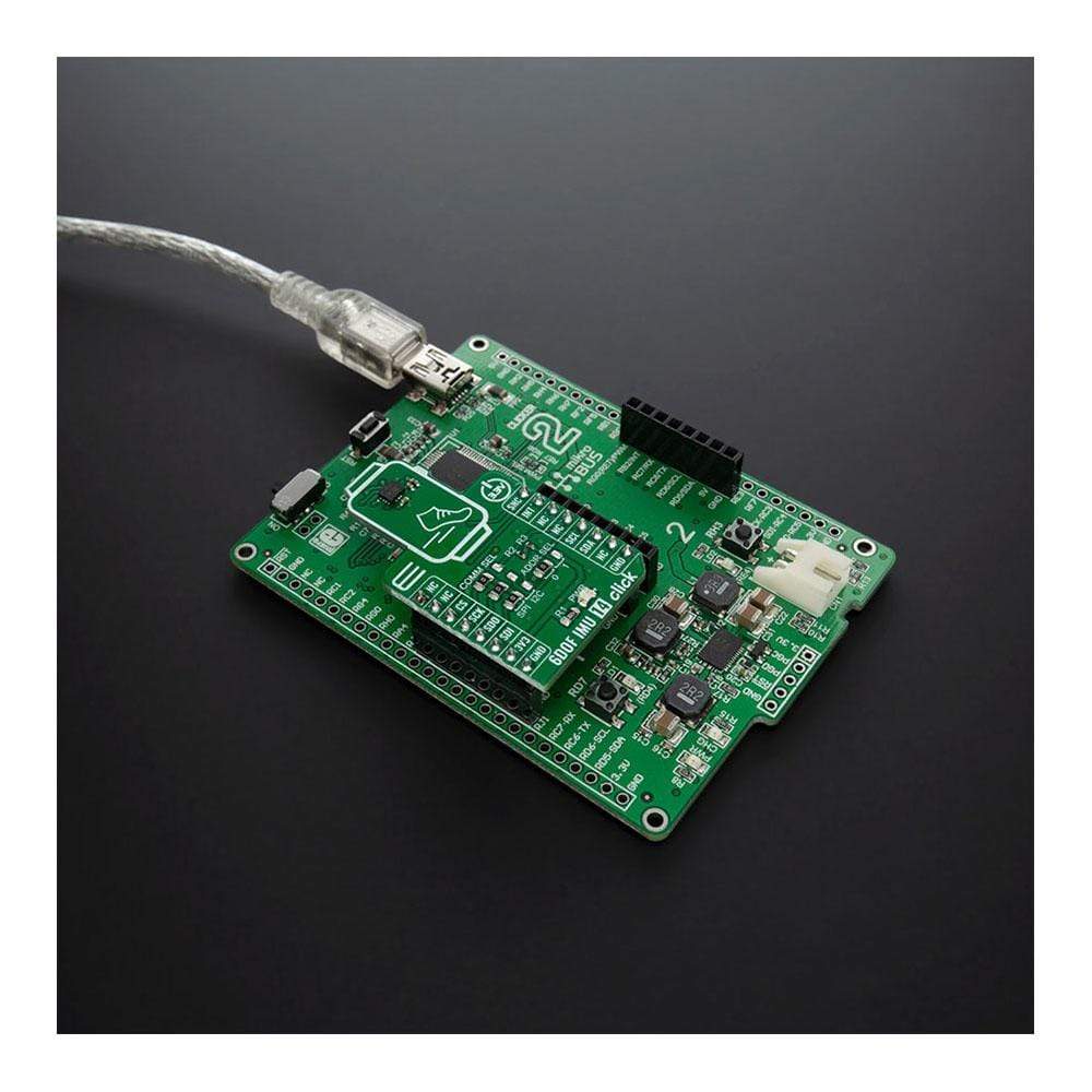
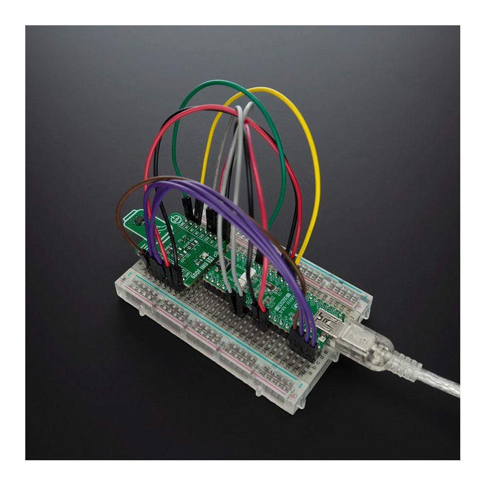
Das 6DOF IMU 14 Click wird von einer mikroSDK-kompatiblen Bibliothek unterstützt, die Funktionen enthält, die die Softwareentwicklung vereinfachen. Dieses Click Board™ wird als vollständig getestetes Produkt geliefert und ist bereit für den Einsatz auf einem System, das mit der mikroBUS™-Buchse ausgestattet ist.
How Does The 6DOF IMU 14 Click Board™ Work?
The 6DOF IMU 14 Click Board™ is based on the ICM-42688-P, high precision 6-axis MEMS motion tracking device, from TDK InvenSense. It features a 2kB FIFO that can lower the traffic on the serial bus interface, and reduce power consumption by allowing the system processor to burst read sensor data, and then go into a low-power mode. It also supports external clock input for highly accurate 31kHz to 50kHz clock, which helps to reduce system-level sensitivity error and improve orientation measurement from gyroscope data. ICM-42688-P includes an industry-first 20-bits data format support in FIFO for high-data resolution. This FIFO format encapsulates 19-bits of gyroscope data and 18-bits of accelerometer data.
The 6DOF IMU 14 Click Board™ includes a vibratory MEMS rate gyroscope that detects rotation about the X-, Y-, and Z- axes, and a 3-axis MEMS accelerometer. The full-scale range of the gyro sensors may be digitally programmed from ±15.625 up to ±2000 degrees per second (DPS). The ICM-42688-P architecture reduces the accelerometer's sensitivity to fabrication variations as well as to thermal drift. When the device is placed on a flat surface, it will measure 0g on the X- and Y-axes and +1g on the Z-axis. The full-scale range of the digital output can be adjusted from ±2g, up to ±16g.
The ICM-42688-P has a programmable interrupt system that can generate an interrupt signal. There are two interrupt outputs in which one of them represents frame synchronization input routed to the PWM pins on the mikroBUS™. An interrupt can be triggered while switching clock sources, when new data is available for reading (from the FIFO and data registers), during accelerometer events, FIFO watermark and overflow.
6DOF IMU 14 Click provides the possibility of using both I2C and SPI interfaces with a maximum frequency of 1MHz for I2C and 25MHz for SPI communication. The selection can be done by positioning SMD jumpers labeled as COMM SEL to an appropriate position. Note that all the jumpers must be placed to the same side, or else the Click board™ may become unresponsive. While the I2C interface is selected, the ICM-42688-P allows the choice of the least significant bit (LSB) of its I2C slave address. This can be done by using the SMD jumper labeled as ADDR SEL.
This Click Board™ is designed to be operated only with a 3.3V logic level. A proper logic voltage level conversion should be performed before the Click board™ is used with MCUs with different logic levels.
SPECIFICATIONS
Type | Motion |
Applications | Can be used for applications like gesture recognition, activity classification, and pedometer, along with programmable digital filters, and an embedded temperature sensor. |
On-board modules | 6DOF IMU 14 Click is based on the ICM-42688-P, high precision 6-axis MEMS motion tracking device, from TDK InvenSense. |
Key Features | Low power consumption, high precission, user-programmable digital filters, user scallable gyro/accel full-scale range, 20,000 g shock tolerant and more. |
Interface | I2C,SPI |
Compatibility | mikroBUS |
Click board size | S (28.6 x 25.4 mm) |
Input Voltage | 3.3V |
PINOUT DIAGRAM
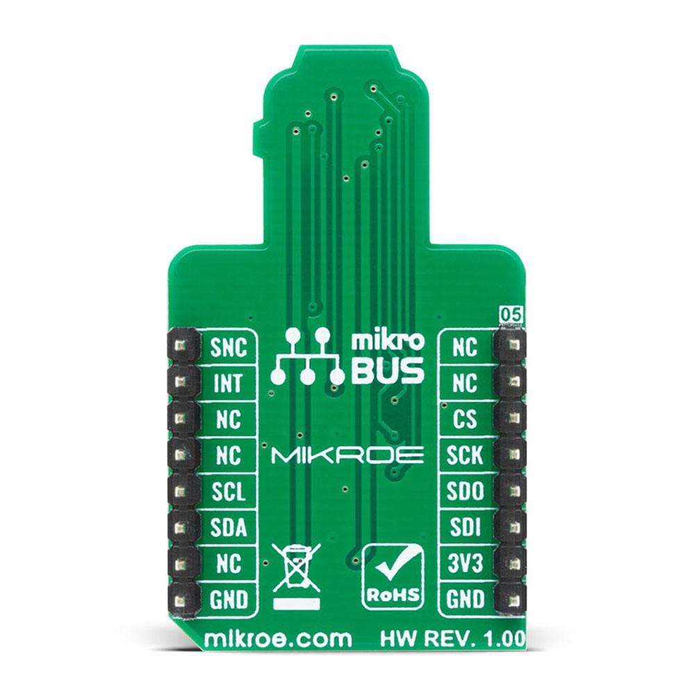
This table shows how the pinout on 6DOF IMU 14 Click corresponds to the pinout on the mikroBUS™ socket (the latter shown in the two middle columns).
Notes | Pin | Pin | Notes | ||||
---|---|---|---|---|---|---|---|
NC | 1 | AN | PWM | 16 | SNC | External sync | |
NC | 2 | RST | INT | 15 | INT | Interrupt | |
SPI Chip Select | CS | 3 | CS | RX | 14 | NC | |
SPI Clock | SCK | 4 | SCK | TX | 13 | NC | |
SPI Data OUT | SDO | 5 | MISO | SCL | 12 | SCL | I2C Clock |
SPI Data IN | SDI | 6 | MOSI | SDA | 11 | SDA | I2C Data |
Power Supply | 3.3V | 7 | 3.3V | 5V | 10 | NC | |
Ground | GND | 8 | GND | GND | 9 | GND | Ground |
ONBOARD SETTINGS AND INDICATORS
Label | Name | Default | Description |
---|---|---|---|
LD1 | PWR | - | Power LED Indicator |
JP1 | ADDR SEL | Left | I2C Address Selection: Left position 0, Right position 1 |
JP2-JP4 | COMM SEL | Left | Communication Interface Selection: Left position SPI, Right position I2C |
6DOF IMU 14 CLICK ELECTRICAL SPECIFICATIONS
Description | Min | Typ | Max | Unit |
---|---|---|---|---|
Supply Voltage | -0.5 | 3.3 | 4 | V |
I2C Clock Frequency | - | - | 1 | MHz |
SPI Clock Frequency | - | - | 24 | MHz |
External Clock Source | 31 | 32 | 50 | kHz |
Operating Temperature Range | -40 | - | +85 | °C |
We provide a library for the 6DOF IMU 14 Click on our LibStock page, as well as a demo application (example), developed using MikroElektronika compilers. The demo can run on all the main MikroElektronika development boards.
Library Description
The library contains a basic functions for using 6DOF IMU 14 click.
Key Functions
void c6dofimu14_get_gyro_axis ( c6dofimu14_axis_t *axis )
- Gets GYRO XYZ axis valuevoid c6dofimu14_get_accel_axis ( c6dofimu14_axis_t *axis )
- Gets ACCEL XYZ axis valuefloat c6dofimu14_get_temperature ( void )
- Gets Temperature value
Example Description
The application is composed of three sections :
- System Initialization - Initializes I2C or SPI module and all necessary GPIO pins
- Application Initialization - Initializes driver inti, configuration module for measurement and cheeks communication with the module.
- Application Task - Reads Accel, Gyro and Temperature data and logs data to USB UART every 1.5 second.
- Note - For more characteristics and information, you should see the datasheet of the sensor.
void application_task ( ) { float temperature; c6dofimu14_axis_t accel; c6dofimu14_axis_t gyro; mikrobus_logWrite( " ", _LOG_LINE ); // ACCEL DATA c6dofimu14_get_accel_axis( &accel ); FloatToStr( accel.x, demo_text ); mikrobus_logWrite( " >> Accel: X: ", _LOG_TEXT ); mikrobus_logWrite( demo_text, _LOG_TEXT ); FloatToStr( accel.y, demo_text ); mikrobus_logWrite( " Y: ", _LOG_TEXT ); mikrobus_logWrite( demo_text, _LOG_TEXT ); FloatToStr( accel.z, demo_text ); mikrobus_logWrite( " Z: ", _LOG_TEXT ); mikrobus_logWrite( demo_text, _LOG_LINE ); // GYRO DATA c6dofimu14_get_gyro_axis( &gyro ); FloatToStr( gyro.x, demo_text ); mikrobus_logWrite( " >> Gyro: X: ", _LOG_TEXT ); mikrobus_logWrite( demo_text, _LOG_TEXT ); FloatToStr( gyro.y, demo_text ); mikrobus_logWrite( " Y: ", _LOG_TEXT ); mikrobus_logWrite( demo_text, _LOG_TEXT ); FloatToStr( gyro.z, demo_text ); mikrobus_logWrite( " Z: ", _LOG_TEXT ); mikrobus_logWrite( demo_text, _LOG_LINE ); // TEMPERATURE temperature = c6dofimu14_get_temperature( ); FloatToStr( temperature, demo_text ); mikrobus_logWrite( " >> Temperature: ", _LOG_TEXT ); mikrobus_logWrite( demo_text, _LOG_LINE ); mikrobus_logWrite( "--------------------------", _LOG_LINE ); Delay_ms( 1500 );
The full application code, and ready to use projects can be found on our LibStock page.
Other mikroE Libraries used in the example:
- I2C Library
- SPI Library
- Conversions library
Additional Notes and Information
Depending on the development board you are using, you may need USB UART click, USB UART 2 click or RS232 click to connect to your PC, for development systems with no UART to USB interface available on the board. The terminal available in all MikroElektronika compilers, or any other terminal application of your choice, can be used to read the message.
MIKROSDK
This Click board™ is supported with mikroSDK - MikroElektronika Software Development Kit. To ensure proper operation of mikroSDK compliant Click board™ demo applications, mikroSDK should be downloaded from the LibStock and installed for the compiler you are using.
Frequently Asked Questions
Have a Question?
Be the first to ask a question about this.