


Mikroelektronika d.o.o.
6DOF IMU 13 Click-Platine
6DOF IMU 13 Click-Platine
SKU: MIKROE-4228
Verfügbarkeit für Abholungen konnte nicht geladen werden
Overview
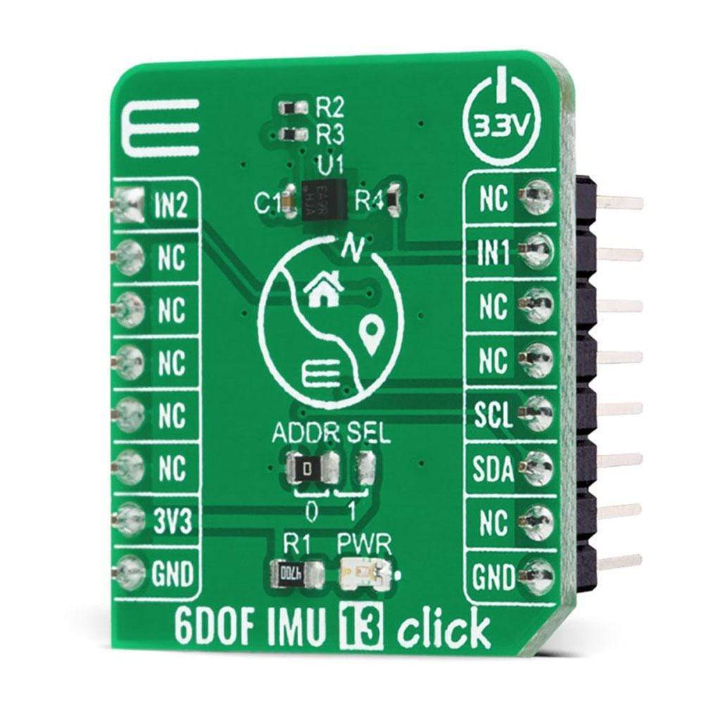
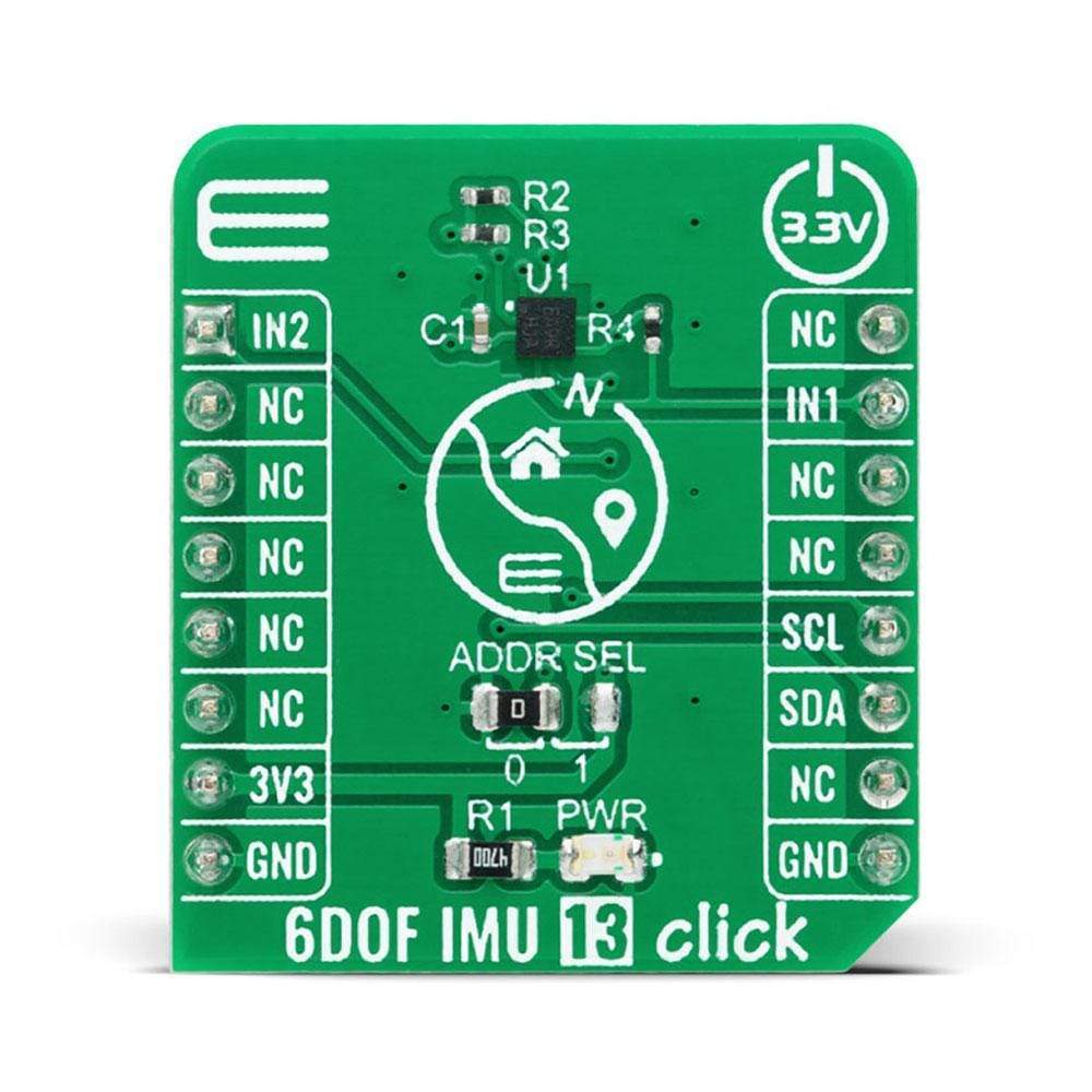
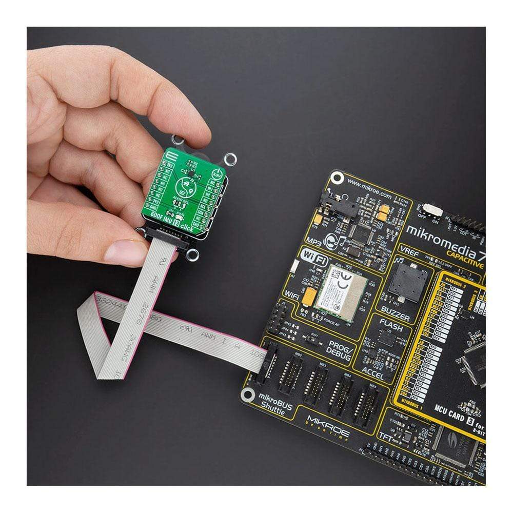
The 6DOF IMU 13 Click Board™ is a compact add-on board that contains an eCompass that consists of a 3-axis linear accelerometer and a 3-axis magnetic field sensor. This board features the MC6470, an accelerometer and magnetometer for a 6 DoF (6 Degrees of Freedom) sensor solution, from mCube Inc. It has a linear acceleration full-scale range of ±16g and a low noise magnetic sensor with up to 0.15μT magnetic field resolution, with a single I2C interface available to separately control magnetometer and accelerometer functions, enabling independent operation of functions for application flexibility. This Click Board™ is an excellent choice for applications requiring high-precision directional pointing such as map orientation, virtual reality data overlay, enhanced navigation, and gyroscope replacement.
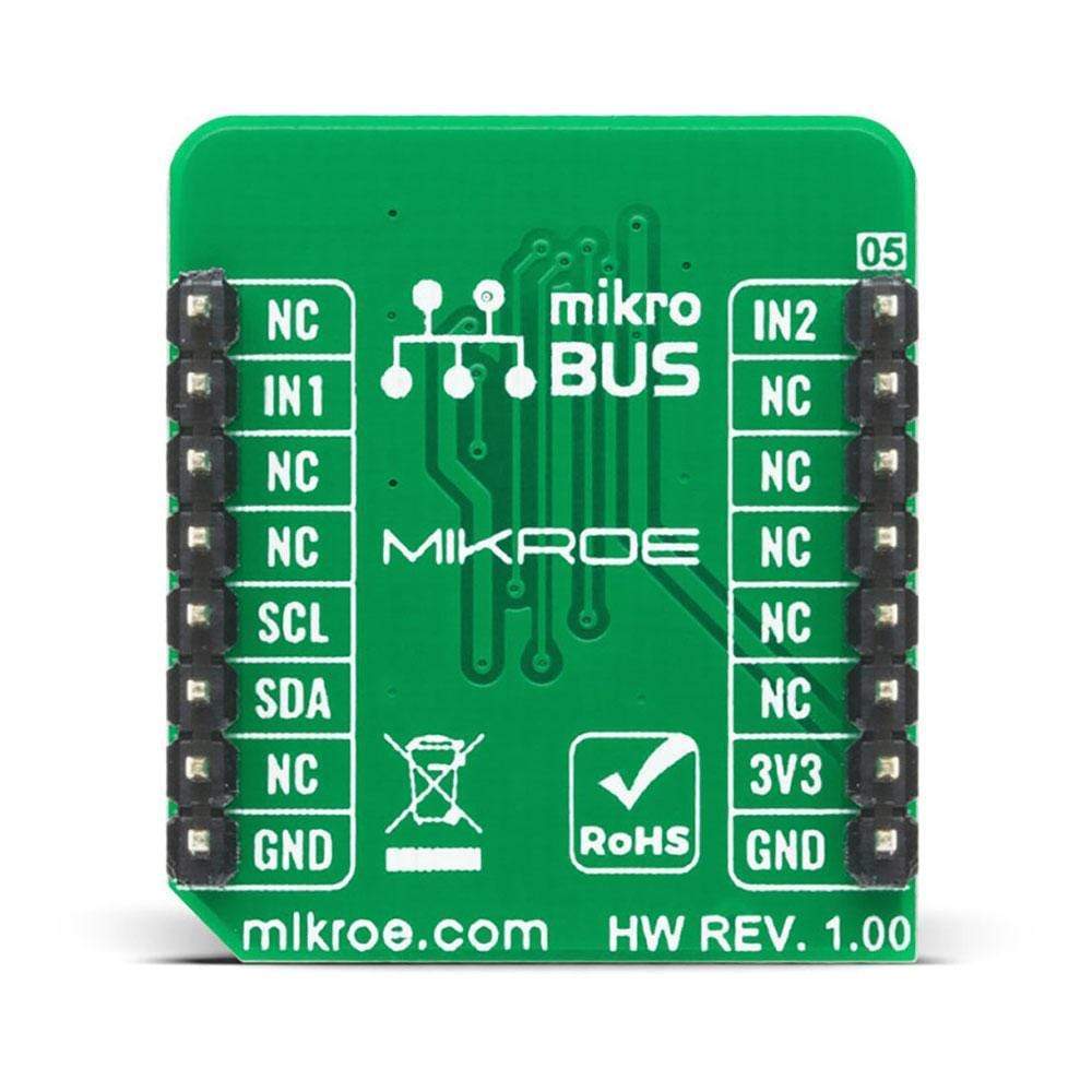
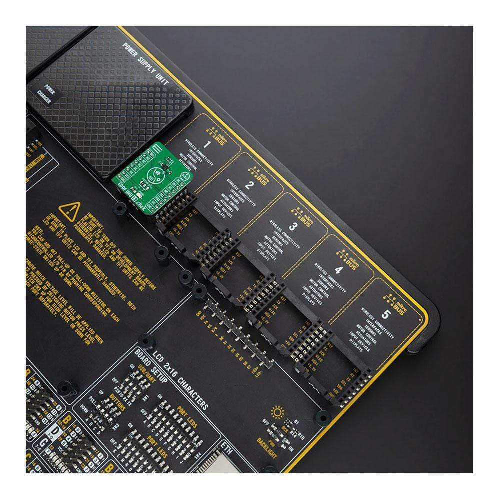
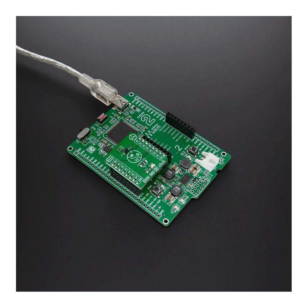
The 6DOF IMU 13 Click is supported by a mikroSDK-compliant library, which includes functions that simplify software development. This Click Board™ comes as a thoroughly tested product, ready to be used on a system equipped with the mikroBUS™ socket.
Downloads
Das 6DOF IMU 13 Click Board™ ist eine kompakte Zusatzplatine, die einen eCompass enthält, der aus einem 3-Achsen-Linearbeschleunigungsmesser und einem 3-Achsen-Magnetfeldsensor besteht. Diese Platine verfügt über den MC6470, einen Beschleunigungsmesser und Magnetometer für eine 6-DoF-Sensorlösung (6 Freiheitsgrade) von mCube Inc. Es verfügt über einen linearen Beschleunigungsbereich von ±16 g und einen rauscharmen Magnetsensor mit einer Magnetfeldauflösung von bis zu 0,15 μT, mit einer einzigen I2C-Schnittstelle zur separaten Steuerung der Magnetometer- und Beschleunigungsmesserfunktionen, die einen unabhängigen Betrieb der Funktionen für Anwendungsflexibilität ermöglicht. Dieses Click Board™ ist eine ausgezeichnete Wahl für Anwendungen, die eine hochpräzise Richtungsanzeige erfordern, wie z. B. Kartenausrichtung, Virtual-Reality-Datenüberlagerung, verbesserte Navigation und Gyroskopersatz.
Das 6DOF IMU 13 Click wird von einer mikroSDK-kompatiblen Bibliothek unterstützt, die Funktionen enthält, die die Softwareentwicklung vereinfachen. Dieses Click Board™ ist ein gründlich getestetes Produkt und kann auf einem System verwendet werden, das mit der mikroBUS™-Buchse ausgestattet ist.
| General Information | |
|---|---|
Part Number (SKU) |
MIKROE-4228
|
Manufacturer |
|
| Physical and Mechanical | |
Weight |
0.017 kg
|
| Other | |
EAN |
8606027380280
|
Frequently Asked Questions
Have a Question?
Be the first to ask a question about this.