

Mikroelektronika d.o.o.
SPI Extend Click-Platine
SPI Extend Click-Platine
SKU: MIKROE-4184
Verfügbarkeit für Abholungen konnte nicht geladen werden


Overview
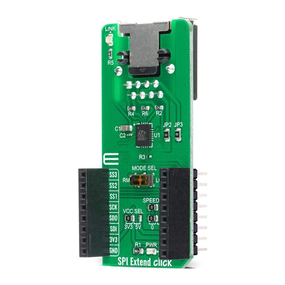
The SPI Extend Click Board™ is a compact add-on board for applications that require extending the SPI communication bus over a long distance. This board features the LTC4332, an SPI slave extender device, from Analog Devices. Using a ±60V fault protected differential transceiver, the LTC4332 can transmit SPI data, including an interrupt signal, up to 2MHz over two twisted-pair cables. The extended common-mode range and high common-mode rejection on the differential link provide tolerance to large ground differences between nodes. This Click Board™ also provides a control interface using a separate slave select for configuration and fault monitoring. All these features make SPI Extend Click an excellent choice for various applications that require extending the SPI bus over a long distance, such as industrial control, sensor installations, lighting and sound system control, and more.
The SPI Extend Click Board™ is supported by a mikroSDK compliant library, which includes functions that simplify software development. This Click Board™ comes as a fully tested product, ready to be used on a system equipped with the mikroBUS™ socket.
Downloads
Das SPI Extend Click Board™ ist eine kompakte Zusatzplatine für Anwendungen, bei denen der SPI-Kommunikationsbus über eine große Distanz verlängert werden muss. Diese Platine verfügt über den LTC4332, ein SPI-Slave-Extender-Gerät von Analog Devices. Mithilfe eines ±60-V-Fehlerschutz-Differential-Transceivers kann der LTC4332 SPI-Daten, einschließlich eines Interrupt-Signals, mit bis zu 2 MHz über zwei Twisted-Pair-Kabel übertragen. Der erweiterte Gleichtaktbereich und die hohe Gleichtaktunterdrückung auf der Differenzialverbindung sorgen für Toleranz gegenüber großen Masseunterschieden zwischen Knoten. Dieses Click Board™ bietet außerdem eine Steuerschnittstelle mit einer separaten Slave-Auswahl für Konfiguration und Fehlerüberwachung. All diese Funktionen machen SPI Extend Click zu einer ausgezeichneten Wahl für verschiedene Anwendungen, bei denen der SPI-Bus über eine große Distanz verlängert werden muss, wie z. B. Industriesteuerung, Sensorinstallationen, Beleuchtungs- und Soundsystemsteuerung und mehr.
Das SPI Extend Click Board™ wird von einer mikroSDK-kompatiblen Bibliothek unterstützt, die Funktionen enthält, die die Softwareentwicklung vereinfachen. Dieses Click Board™ wird als vollständig getestetes Produkt geliefert und ist bereit für den Einsatz auf einem System, das mit der mikroBUS™-Buchse ausgestattet ist.
| General Information | |
|---|---|
Part Number (SKU) |
MIKROE-4184
|
Manufacturer |
|
| Physical and Mechanical | |
Weight |
0.023 kg
|
| Other | |
EAN |
8606027380174
|
Frequently Asked Questions
Have a Question?
Be the first to ask a question about this.