


Mikroelektronika d.o.o.
ISO ADC 2 Click-Platine
ISO ADC 2 Click-Platine
SKU: MIKROE-4166
Verfügbarkeit für Abholungen konnte nicht geladen werden


Overview
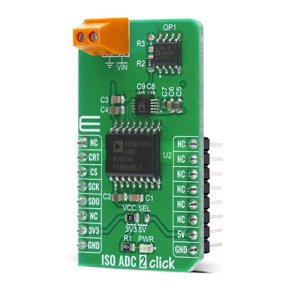
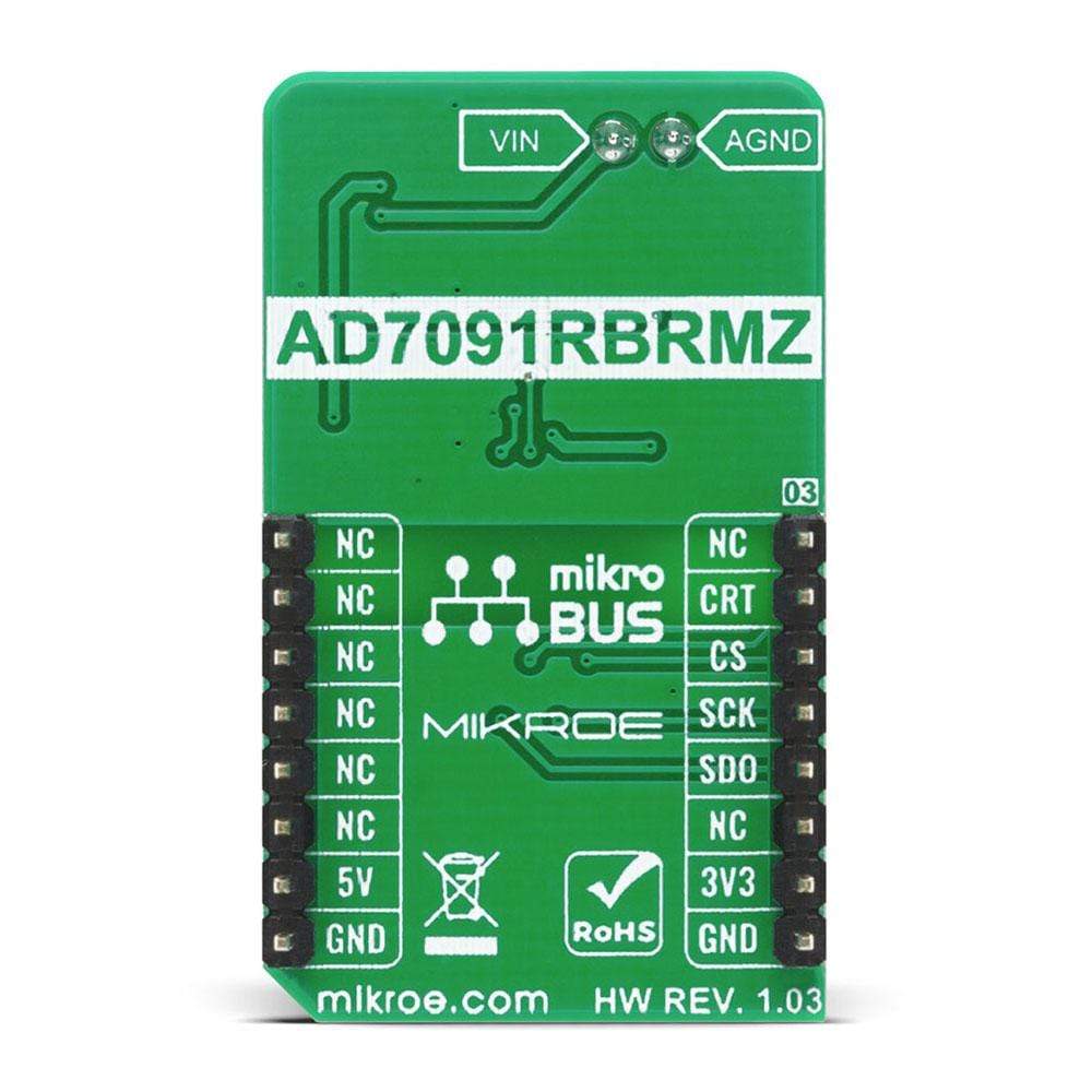
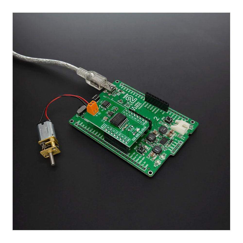
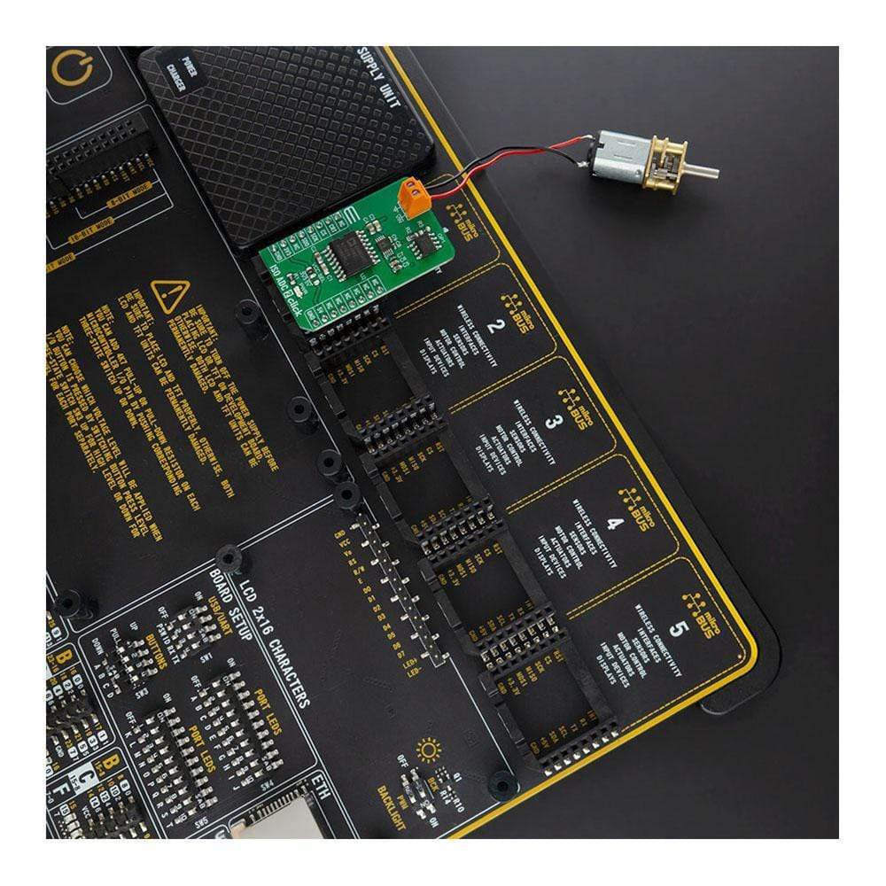
The ISO ADC 2 Click Board™ is a compact add-on board that represents a completely isolated 12-bit, 300 kSPS data acquisition system. This board features the AD7091R, a successive-approximation analog-to-digital converter (ADC) from Analog Devices. It uses the 3-wire SPI serial interface for data communication, achieving up to 1 MSPS throughput rate. This Click Board™ also features the ADU 4-Channel Isolator with DC-DC Converter M5401, isolated DC-DC converter used to isolate the logic signals, power, and feedback paths in the DC-DC converter resulting in total isolation solution. Many features such as high throughput rate with ultralow power consumption, wide input bandwidth, accuracy, and speed make it an ideal choice for a wide variety of industrial measurements, data acquisition systems, monitoring functions, and many more.
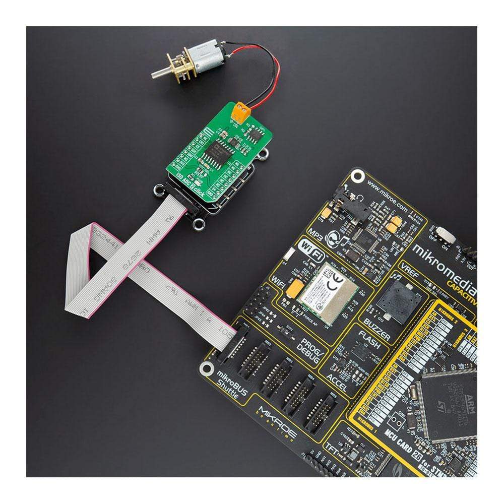
The ISO ADC 2 Click Board™ is supported by a mikroSDK compliant library, which includes functions that simplify software development. This Click Board™ comes as a fully tested product, ready to be used on a system equipped with the mikroBUS™ socket.
Downloads
Das I SO ADC 2 Click Board™ ist eine kompakte Zusatzplatine, die ein vollständig isoliertes 12-Bit-, 300-kSPS-Datenerfassungssystem darstellt. Diese Platine verfügt über den AD7091R, einen Analog-Digital-Wandler (ADC) mit sukzessiver Approximation von Analog Devices. Es verwendet die 3-adrige serielle SPI-Schnittstelle für die Datenkommunikation und erreicht eine Durchsatzrate von bis zu 1 MSPS. Dieses Click Board™ verfügt außerdem über den ADU 4-Kanal-Isolator mit DC-DC-Wandler M5401, einen isolierten DC-DC-Wandler, der zur Isolierung der Logiksignale, der Stromversorgung und der Rückkopplungspfade im DC-DC-Wandler verwendet wird, was zu einer vollständigen Isolationslösung führt. Viele Funktionen wie hohe Durchsatzrate bei extrem niedrigem Stromverbrauch, große Eingangsbandbreite, Genauigkeit und Geschwindigkeit machen es zur idealen Wahl für eine Vielzahl von industriellen Messungen, Datenerfassungssystemen, Überwachungsfunktionen und vielem mehr.
Das ISO ADC 2 Click Board™ wird von einer mikroSDK-kompatiblen Bibliothek unterstützt, die Funktionen enthält, die die Softwareentwicklung vereinfachen. Dieses Click Board™ wird als vollständig getestetes Produkt geliefert und ist bereit für den Einsatz auf einem System, das mit der mikroBUS™-Buchse ausgestattet ist.
| General Information | |
|---|---|
Part Number (SKU) |
MIKROE-4166
|
Manufacturer |
|
| Physical and Mechanical | |
Weight |
0.019 kg
|
| Other | |
EAN |
8606027380266
|
Frequently Asked Questions
Have a Question?
Be the first to ask a question about this.