


Mikroelektronika d.o.o.
9DOF 2 Click-Platine
9DOF 2 Click-Platine
SKU: MIKROE-4128
Verfügbarkeit für Abholungen konnte nicht geladen werden


Overview
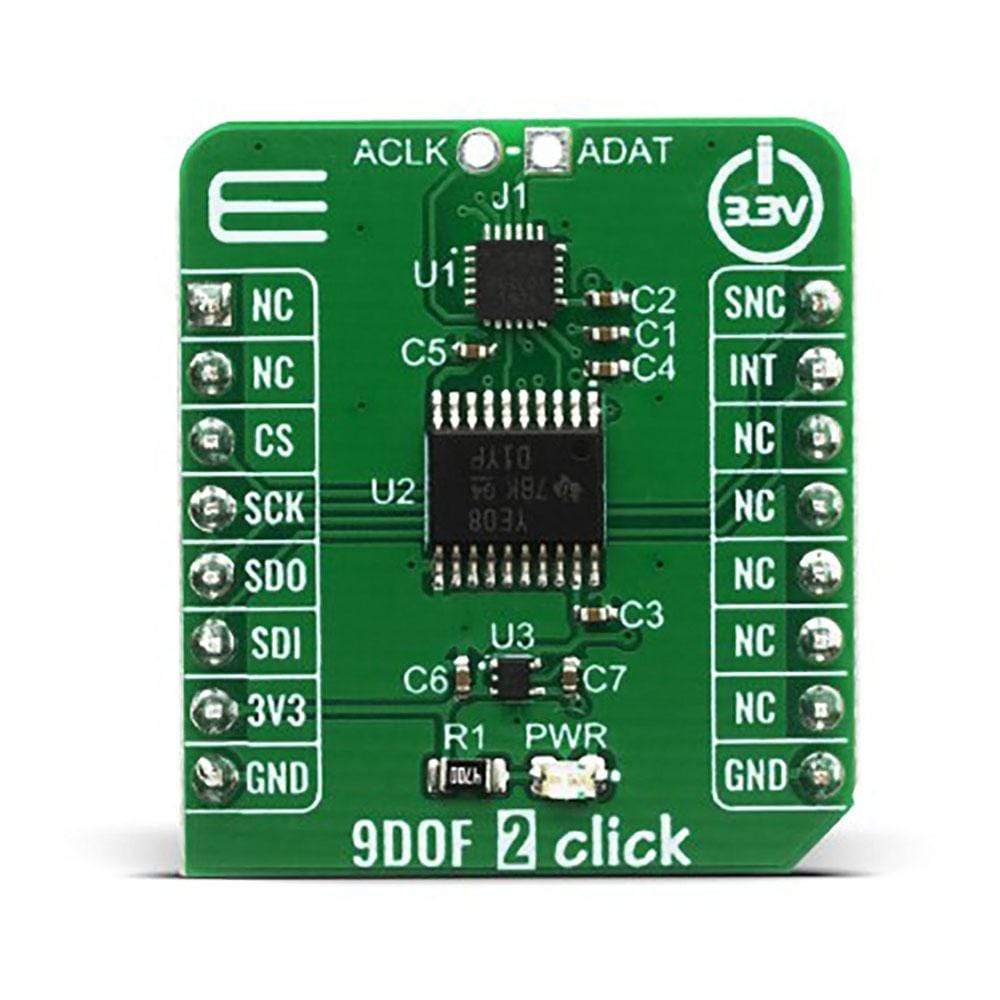
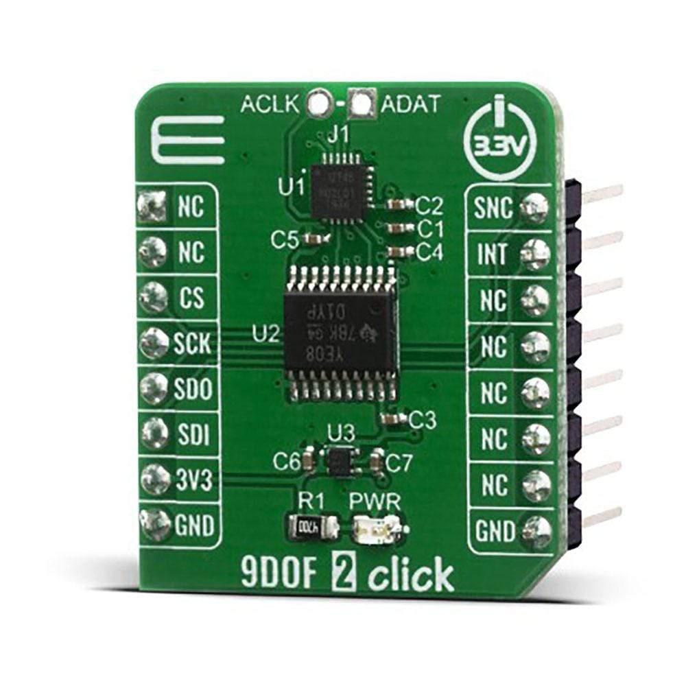
The 9DOF 2 Click Board™ is a compact add-on board for applications that require the lowest power motion tracking and magnetometer functionality. This board features the ICM-20948 a 9-axis MotionTracking™ sensor from TDK Invensense, which consist of two sensors combined into one package for a universal 9DOF solution. In this package, we have a 3-axis gyroscope, a 3-axis accelerometer, a 3-axis magnetometer, combined with Digital Motion Processor™ (DMP) and run-time calibration firmware. All these features make the 9DOF 2 Click Board™ an excellent choice for manufacturers looking for a product to eliminate the costly and complex selection, qualification, and system-level integration of discrete devices, guaranteeing optimal motion performance for consumers. Its also ideally suited for wearable sensors and IoT applications needed low power motion tracking device expandable with additional I2C sensors.
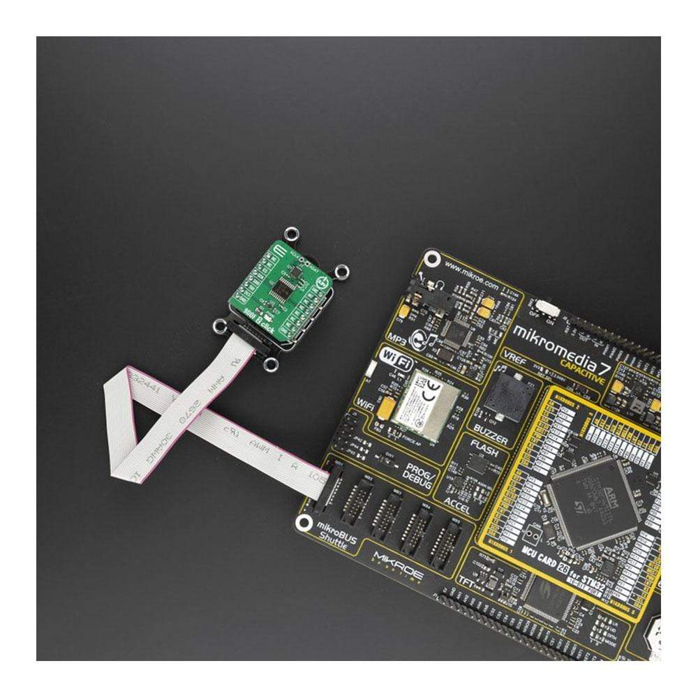
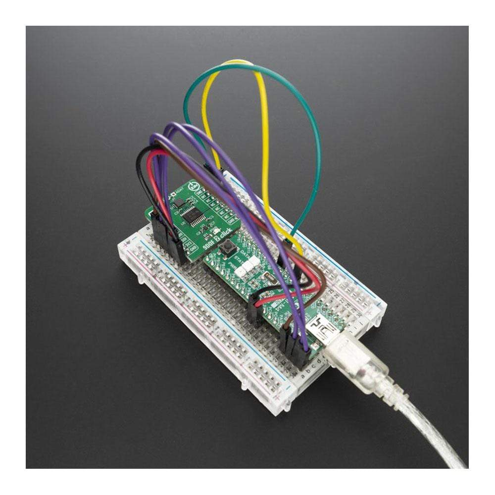
The 9DOF 2 Click Board™ is supported by a mikroSDK compliant library, which includes functions that simplify software development. This Click Board™ comes as a fully tested product, ready to be used on a system equipped with the mikroBUS™ socket.
Downloads
Das 9DOF 2 Click Board™ ist eine kompakte Zusatzplatine für Anwendungen, die Bewegungsverfolgung und Magnetometerfunktionalität mit geringstem Stromverbrauch erfordern. Diese Platine verfügt über den ICM-20948, einen 9-achsigen MotionTracking™-Sensor von TDK Invensense, der aus zwei Sensoren besteht, die in einem Paket für eine universelle 9DOF-Lösung kombiniert sind. In diesem Paket haben wir ein 3-achsiges Gyroskop, einen 3-achsigen Beschleunigungsmesser, ein 3-achsiges Magnetometer, kombiniert mit Digital Motion Processor™ (DMP) und Laufzeitkalibrierungs-Firmware. All diese Funktionen machen das 9DOF 2 Click Board™ zu einer ausgezeichneten Wahl für Hersteller, die nach einem Produkt suchen, um die kostspielige und komplexe Auswahl, Qualifizierung und Integration diskreter Geräte auf Systemebene zu vermeiden und so eine optimale Bewegungsleistung für Verbraucher zu gewährleisten. Es ist auch ideal für tragbare Sensoren und IoT-Anwendungen geeignet, die ein stromsparendes Bewegungsverfolgungsgerät benötigen, das mit zusätzlichen I2C-Sensoren erweiterbar ist.
Das 9DOF 2 Click Board™ wird von einer mikroSDK-kompatiblen Bibliothek unterstützt, die Funktionen enthält, die die Softwareentwicklung vereinfachen. Dieses Click Board™ wird als vollständig getestetes Produkt geliefert und ist bereit für den Einsatz auf einem System, das mit der mikroBUS™-Buchse ausgestattet ist.
| General Information | |
|---|---|
Part Number (SKU) |
MIKROE-4128
|
Manufacturer |
|
| Physical and Mechanical | |
Weight |
0.018 kg
|
| Other | |
EAN |
8606018717538
|
Frequently Asked Questions
Have a Question?
Be the first to ask a question about this.