


Mikroelektronika d.o.o.
I2C MUX 2 Click-Platine
I2C MUX 2 Click-Platine
SKU: MIKROE-4094
Verfügbarkeit für Abholungen konnte nicht geladen werden


Overview
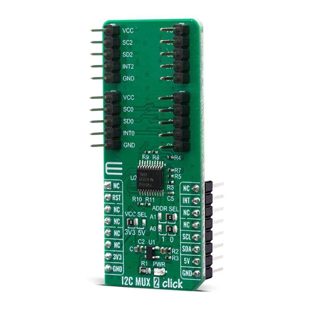
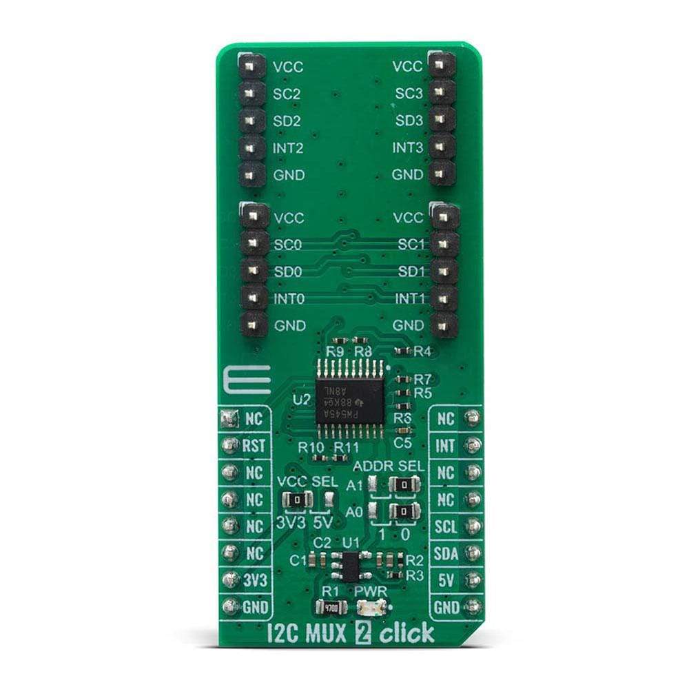
The I2C MUX 2 Click Board™ is a quad bidirectional translating I2C and SMBus switch with reset and interrupt functions, intended for applications with I2C slave address conflicts. It features a quad bidirectional translating switch controlled via the I2C bus, labelled as TCA9545A from Texas Instruments. Four interrupt inputs (INT3–INT0), one for each of the downstream pairs, are provided on the click board. One interrupt (INT) output acts as an AND of the four interrupt inputs. Click has two address jumpers, allowing up to four TCA9545A devices on the same bus. The I2C MUX 2 Click Board™ allows voltage translation between 1.8V, 2.5V, 3.3V, and 5V buses, and also supports hot insertion. The TCA9546A can work on a 0 - 400 kHz clock frequency range and is ideal for communication with numerous devices that share the identical slave address on the same bus.
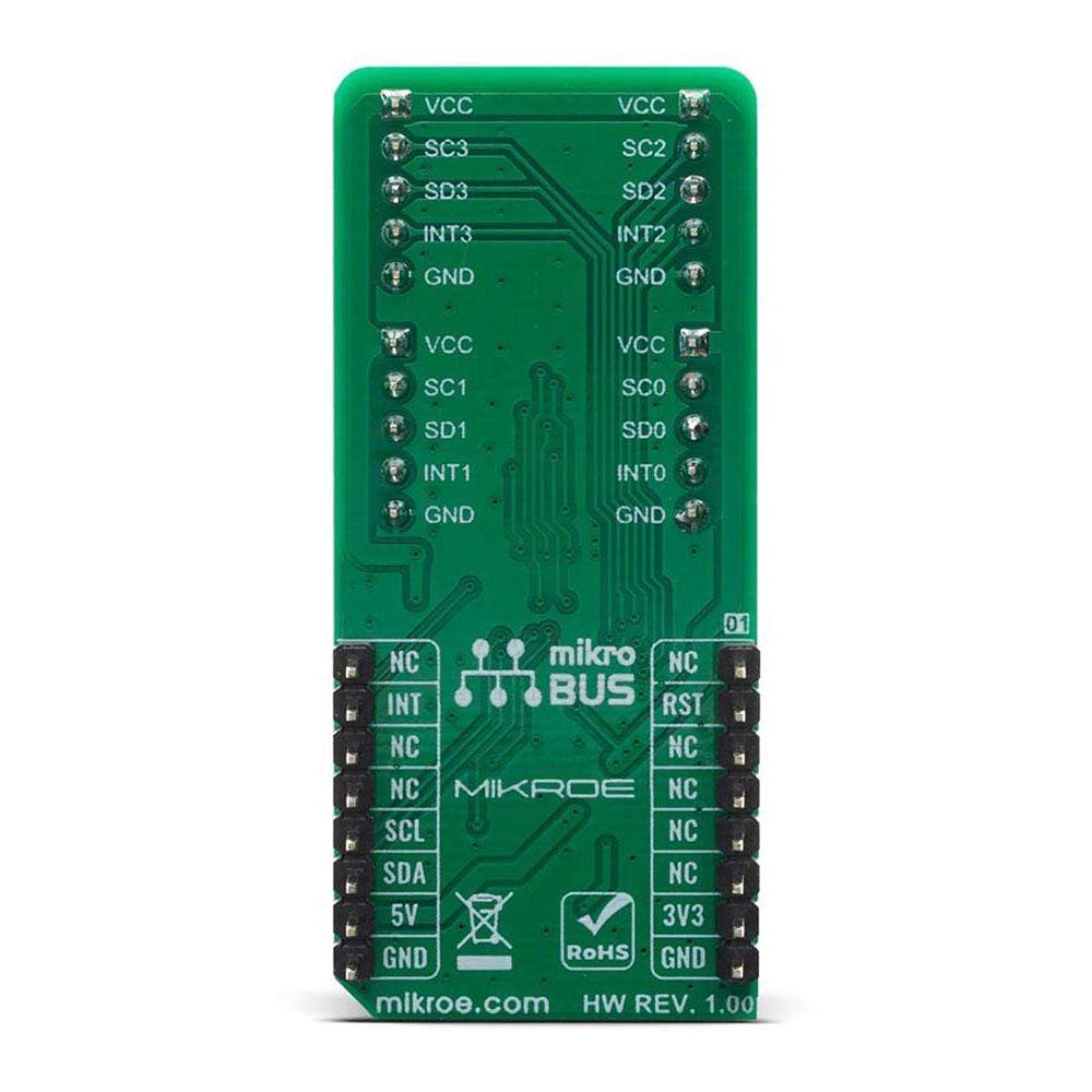
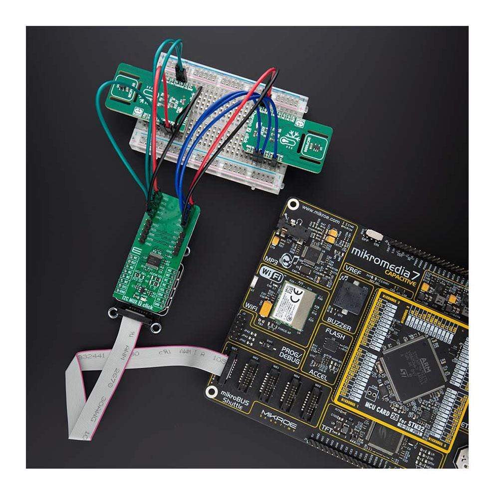
The I2C MUX 2 Click Board™ is supported by a mikroSDK compliant library, which includes functions that simplify software development. This Click Board™ comes as a fully tested product, ready to be used on a system equipped with the mikroBUS™ socket.
Downloads
Das I2C MUX 2 Click Board™ ist ein vierfacher bidirektionaler I2C- und SMBus-Umsetzer mit Reset- und Interrupt-Funktionen, der für Anwendungen mit I2C-Slave-Adresskonflikten vorgesehen ist. Es verfügt über einen vierfachen bidirektionalen Umsetzer, der über den I2C-Bus gesteuert wird und als TCA9545A von Texas Instruments bezeichnet wird. Auf dem Click Board sind vier Interrupt-Eingänge (INT3–INT0) vorgesehen, einer für jedes der nachgeschalteten Paare. Ein Interrupt-Ausgang (INT) fungiert als UND der vier Interrupt-Eingänge. Click verfügt über zwei Adressbrücken, sodass bis zu vier TCA9545A-Geräte auf demselben Bus verwendet werden können. Das I2C MUX 2 Click Board™ ermöglicht die Spannungsumsetzung zwischen 1,8-V-, 2,5-V-, 3,3-V- und 5-V-Bussen und unterstützt auch Hot Insertion. Das TCA9546A kann in einem Taktfrequenzbereich von 0 bis 400 kHz arbeiten und ist ideal für die Kommunikation mit zahlreichen Geräten, die die gleiche Slave-Adresse auf demselben Bus verwenden.
Das I2C MUX 2 Click Board™ wird von einer mikroSDK-kompatiblen Bibliothek unterstützt, die Funktionen enthält, die die Softwareentwicklung vereinfachen. Dieses Click Board™ wird als vollständig getestetes Produkt geliefert und ist bereit für den Einsatz auf einem System, das mit der mikroBUS™-Buchse ausgestattet ist.
| General Information | |
|---|---|
Part Number (SKU) |
MIKROE-4094
|
Manufacturer |
|
| Physical and Mechanical | |
Weight |
0.021 kg
|
| Other | |
EAN |
8606018717347
|
Frequently Asked Questions
Have a Question?
Be the first to ask a question about this.