RNG-Klick-Board
RNG-Klick-Board
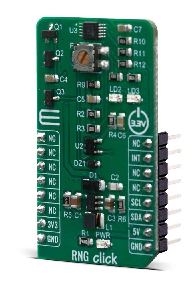
Das RNG Click Board™ ist ein Zufallszahlengenerator (RNG), also ein Gerät, das eine Folge von Zahlen oder Symbolen generiert, die nicht besser als durch Zufall vorhergesagt werden können. Dieses Click Board™ ist ein echter Hardware-Zufallszahlengenerator (HRNG), der echte Zufallszahlen generiert. Zufallszahlengeneratoren finden Anwendung im Glücksspiel, bei statistischen Stichproben, in der Computersimulation, in der Kryptographie, bei vollständig randomisiertem Design und in verschiedenen anderen Bereichen.
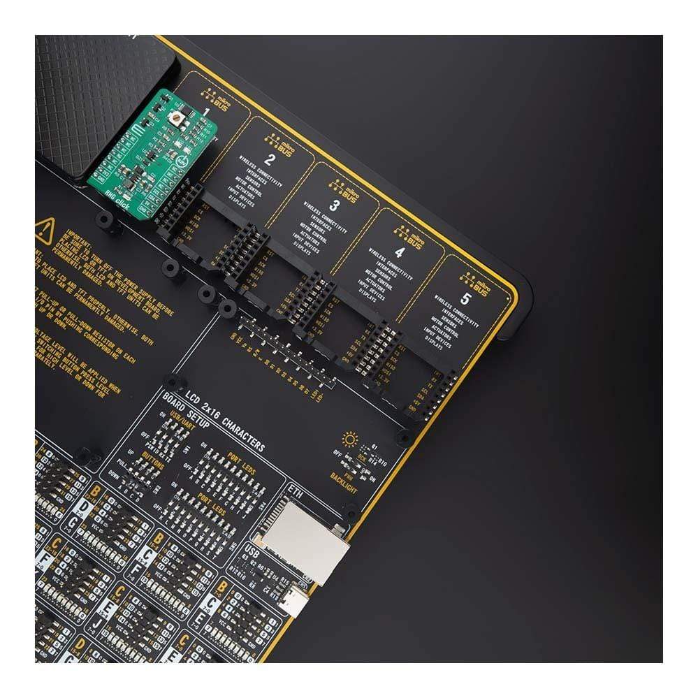
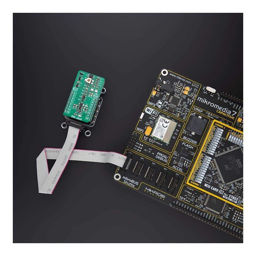
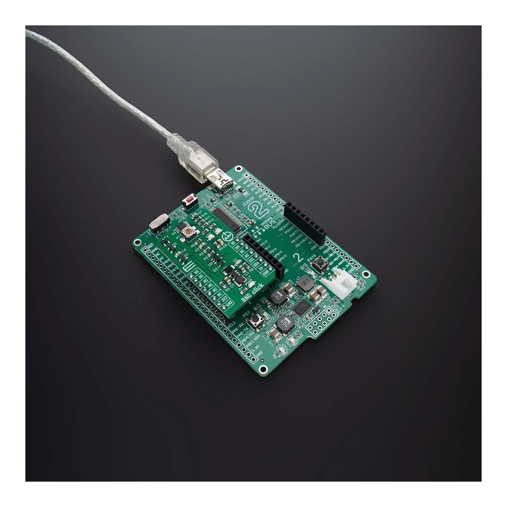
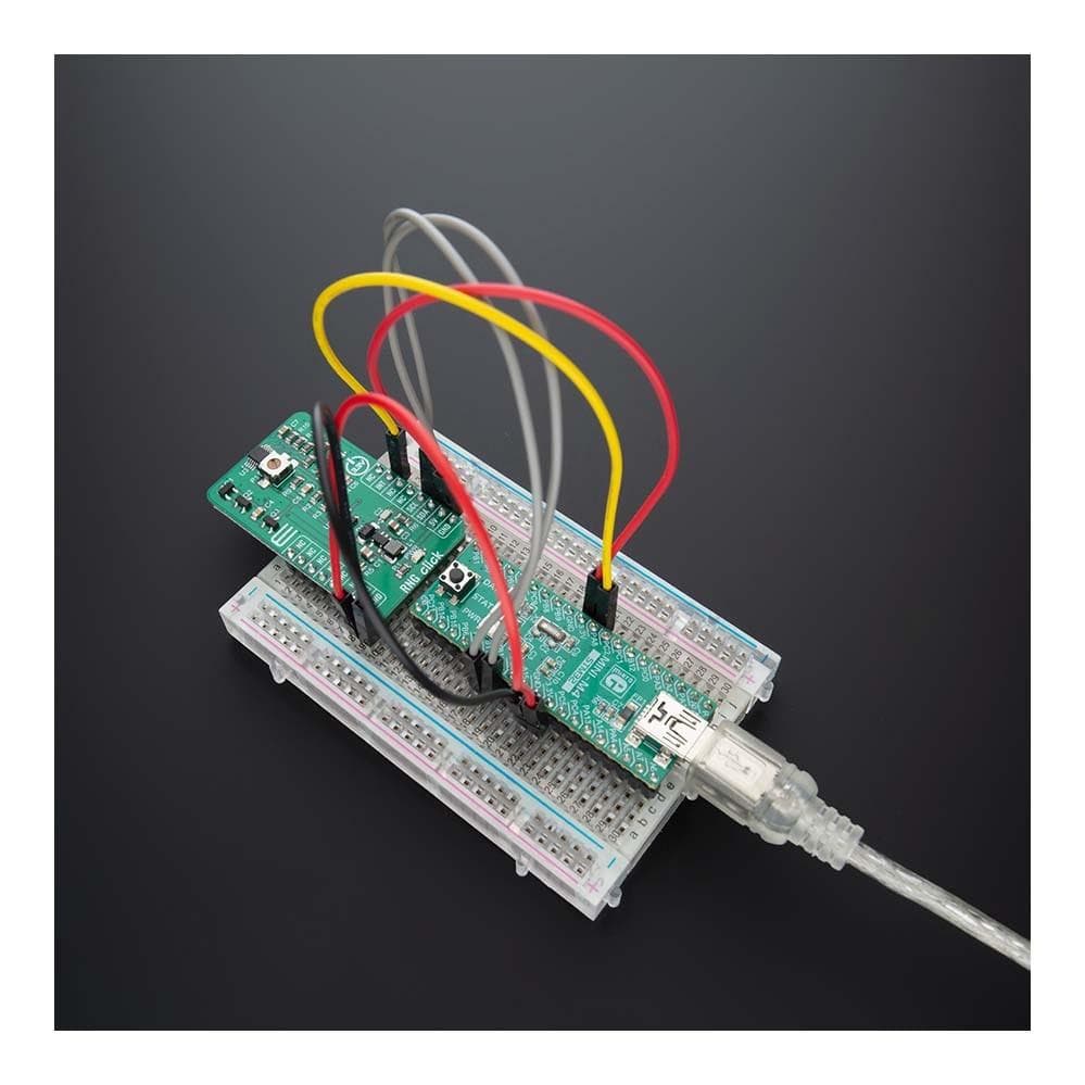
Das RNG Click Board™ wird von einer mikroSDK-kompatiblen Bibliothek unterstützt, die Funktionen enthält, die die Softwareentwicklung vereinfachen. Dieses Click Board™ wird als vollständig getestetes Produkt geliefert und ist bereit für den Einsatz auf einem System, das mit der mikroBUS™-Buchse ausgestattet ist.
How Does The RNG Click Board™ Work?
In computing, a hardware random number generator (HRNG) or true random number generator (TRNG) is a device that generates random numbers from a physical process, rather than by means of an algorithm. Such devices are often based on microscopic phenomena that generate low-level, statistically random "noise" signals, which is the case in this Click board™. That process is, in theory, completely unpredictable, and the theory's assertions of unpredictability are subject to experimental test. This is in contrast to the paradigm of pseudo-random number generation, which is commonly implemented by the software.
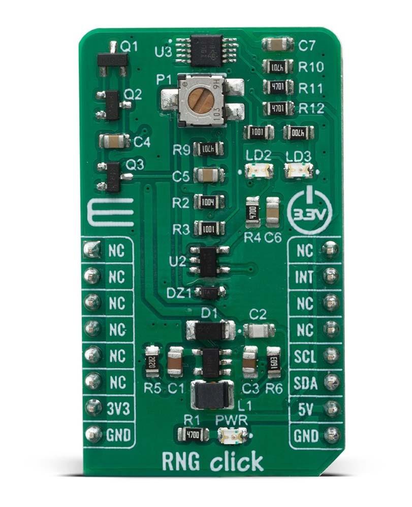
The heart of the RNG Click Board™ is the avalanche noise generated from an internal diode of the transistor Q1 (BC846B). Avalanche breakdown is a phenomenon that can occur in both insulating and semiconducting materials. It is a form of electric current multiplication that can allow very large currents within materials which are otherwise good insulators. The avalanche process occurs when carriers in the transition region are accelerated by the electric field to energies sufficient to create mobile or free electron-hole pairs via collisions with bound electrons. In order to achieve that, RNG click has also boost converter onboard, which is based on TPS61041, from Texas Instruments, and it creates the +18V power supply for the job.
The noise signal, created by the transistors Q1 and Q2 is then amplified with Q3, voltage-limited using the Zener diode and digitalized using the NC7S14M5X inverter, from Fairchild Semiconductor. After that, the string of random ones and zeros is achieved, which is brought to the ADS1115 - 16BIT sigma-delta ADC, from Texas Instruments. The potentiometer P1 is used to set as near as possible distribution of ones and zeros, which is indicated by the LD2 and LD3 LED diodes. The potentiometer P1 should be set in a way that the LD2 and LD3 diodes illuminate as equally as possible. That way, when the single-shot measurement is performed using the ADS1115, over the I2C protocol, the true, 16-bit random number is obtained.
The RNG Click Board™ uses both I2C communication interface. It is designed to be operated only with 3.3V logic levels. A proper logic voltage level conversion should be performed before the Click board™ is used with MCUs with logic levels of 5V.
SPECIFICATIONS
Type | Encryption |
Applications | Gambling, statistical sampling, computer simulation, cryptography, completely randomized design, and various other areas. |
On-board modules | RNG Click uses the noise generator analog circuitry, NC7S14M5X inverter, from Fairchild Semiconductor and the ADS1115 - 16BIT sigma-delta ADC, from Texas Instruments |
Key Features | Random number generator from the analogue signal input. Range of +18V power supply for the number generator range. |
Interface | I2C |
Compatibility | mikroBUS |
Click board size | M (42.9 x 25.4 mm) |
Input Voltage | 3.3V,5V |
PINOUT DIAGRAM
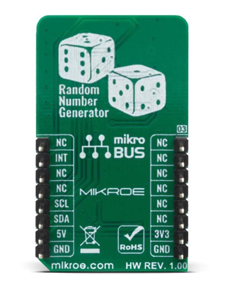
This table shows how the pinout on 6DOF IMU 5 Click corresponds to the pinout on the mikroBUS™ socket (the latter shown in the two middle columns).
Notes | Pin | Pin | Notes | ||||
---|---|---|---|---|---|---|---|
NC | 1 | AN | PWM | 16 | NC | ||
NC | 2 | RST | INT | 15 | INT | Interrupt | |
NC | 3 | CS | RX | 14 | NC | ||
NC | 4 | SCK | TX | 13 | NC | ||
NC | 5 | MISO | SCL | 12 | SCL | I2C Clock | |
NC | 6 | MOSI | SDA | 11 | SDA | I2C Data | |
Power Supply | 3.3V | 7 | 3.3V | 5V | 10 | NC | |
Ground | GND | 8 | GND | GND | 9 | GND | Ground |
ONBOARD SETTINGS AND INDICATORS
Label | Name | Default | Description |
---|---|---|---|
LD1 | PWR | - | Power LED Indicator |
JP2-JP3 | - | - | Ones and zeros distribution indicators |
RS485 4 CLICK ELECTRICAL SPECIFICATIONS
Description | Min | Typ | Max | Unit |
---|---|---|---|---|
Receiver inputs voltage range | - | 16 | - | bit |
Receiver inputs voltage range | 8 | - | 860 | SPS |
Software Support
We provide a library for the RNG Click Board™ on our LibStock page, as well as a demo application (example), developed using MikroElektronika compilers. The demo can run on all the main MikroElektronika development boards.
Library Description
Library contains functions for reading voltage.
Key Functions
void rng_write_data ( uint8_t reg_addr, uint16_t reg_data );
- Generic funcion for writing.void rng_set_config ( uint16_t conf_data );
- Function used for set configuration.float rng_get_voltage ( );
- Function used for get voltage.
Example Description
The application is composed of three sections :
- System Initialization - Initializes i2c module
- Application Initialization - Initializes driver, set configuration and voltage reference.
- Application Task - (code snippet) - Measures voltage every seconds.
void application_task ( ) { char demoText[ 50 ]; float voltage; voltage = rng_get_voltage(); mikrobus_logWrite( " ~~~> Voltage value: ", _LOG_TEXT ); FloatToStr( voltage , demoText ); mikrobus_logWrite( demoText, _LOG_TEXT ); mikrobus_logWrite( " mV ", _LOG_LINE ); mikrobus_logWrite("_______________________________", _LOG_LINE ); mikrobus_logWrite(" ", _LOG_LINE ); Delay_ms( 1000 ); }
The full application code, and ready to use projects can be found on our LibStock page.
Other mikroE Libraries used in the example:
- Conversions
- I2C
- UART
Additional Notes and Information
Depending on the development board you are using, you may need a USB UART click, USB UART 2 click or RS232 click to connect to your PC, for development systems with no UART to USB interface available on the board. The terminal available in all MikroElektronika compilers, or any other terminal application of your choice, can be used to read the message.
MIKROSDK
The RNG Click Board™ is supported with mikroSDK - MikroElektronika Software Development Kit. To ensure proper operation of mikroSDK compliant Click board™ demo applications, mikroSDK should be downloaded from the LibStock and installed for the compiler you are using.
RNG-Klick-Board
Frequently Asked Questions
Have a Question?
Be the first to ask a question about this.