6DOF IMU 5 Click-Platine
Overview
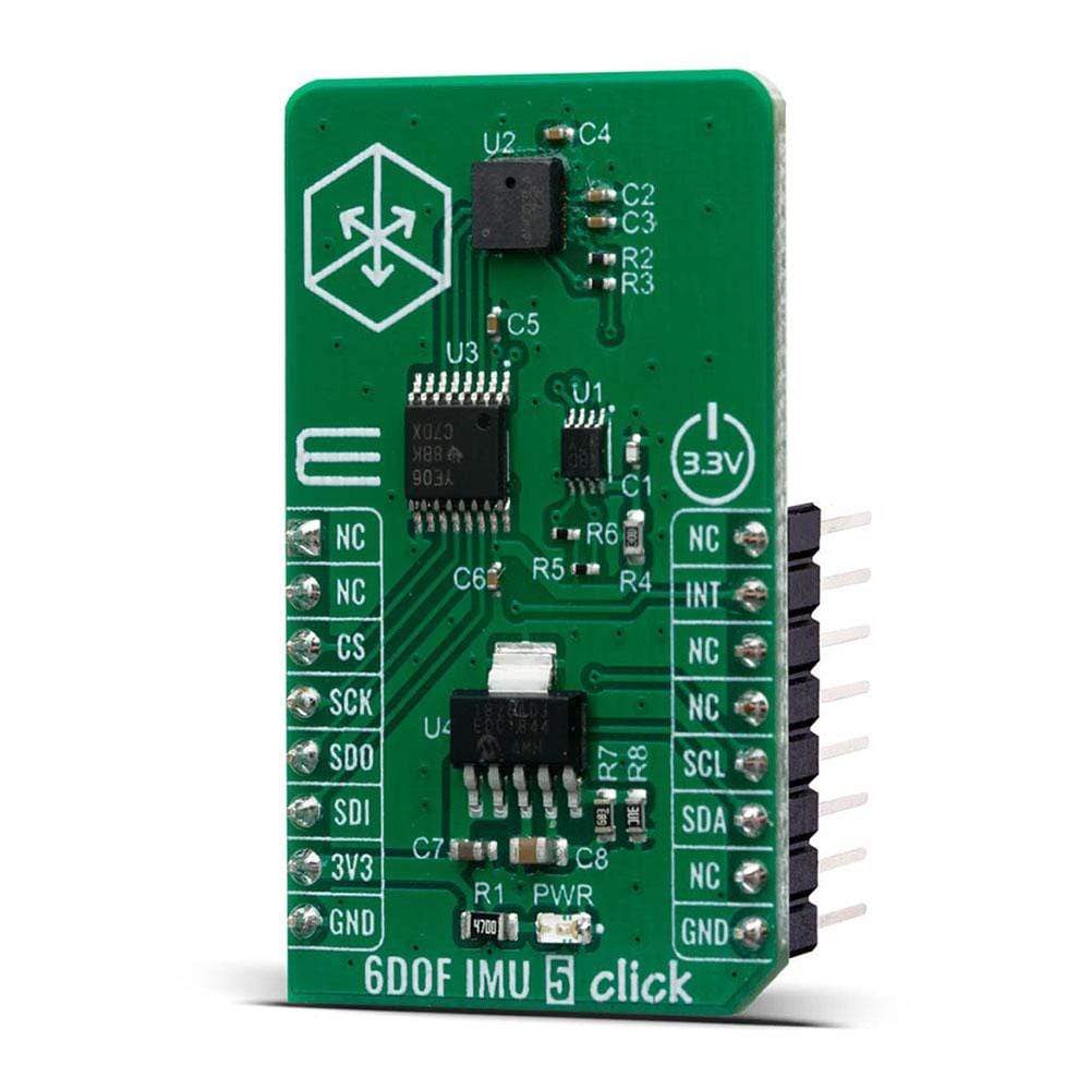
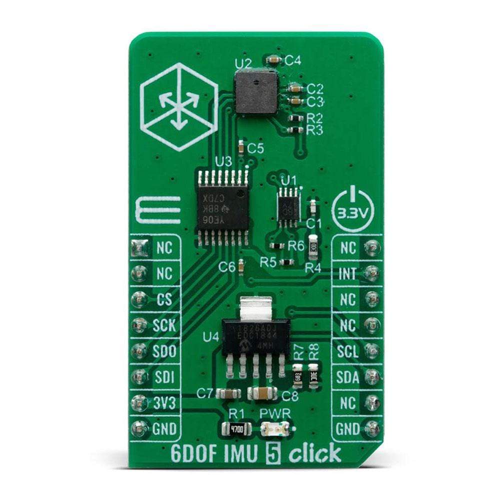
Der 6DOF IMU 5 Click Board™ verfügt über einen 7-Achsen-ICM-20789-Chip von TDK, ein integriertes 6-Achsen-Trägheitsgerät, das ein 3-Achsen-Gyroskop, einen 3-Achsen-Beschleunigungsmesser und einen extrem rauscharmen kapazitiven MEMS-Drucksensor kombiniert. Dieses einzigartige 7-Achsen-Gerät bietet eine hervorragende Leistung mit einer Genauigkeit von ±1 Pa, eine Genauigkeit, die Höhenmessdifferenzen von nur 8,5 cm ermöglicht. Die kapazitive MEMS-Architektur des Drucksensors bietet das branchenweit niedrigste Rauschen bei niedrigstem Stromverbrauch, einen hohen Sensordurchsatz und einen Temperaturkoeffizienten-Offset von ±0,5 Pa/°C. Die Kombination aus hochgenauen Höhenmessungen, geringem Stromverbrauch und Temperaturstabilität macht es ideal für eine breite Palette von Bewegungsverfolgungsanwendungen.
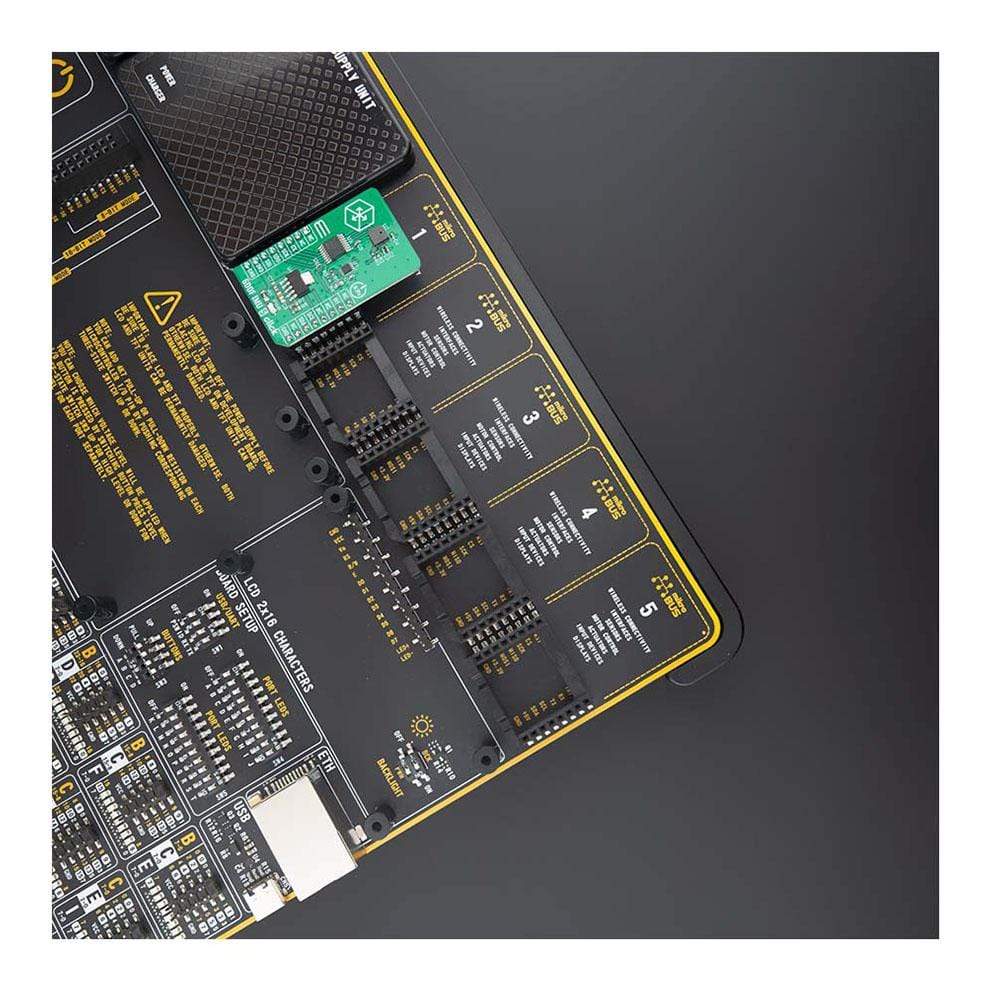
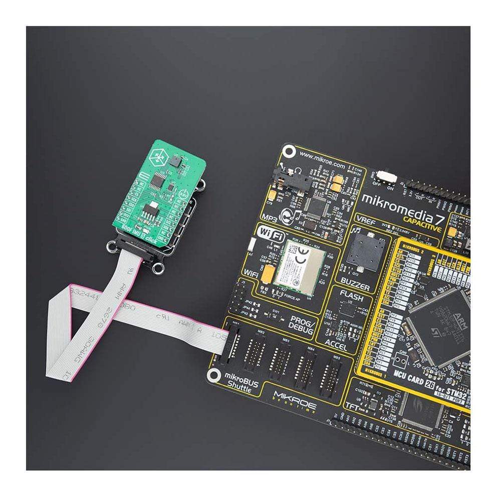
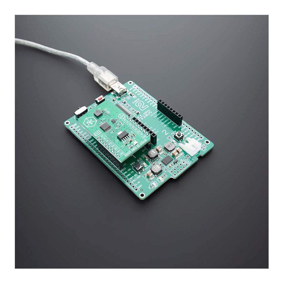
Das 6DOF IMU 5 Click Board wird von einer mikroSDK-kompatiblen Bibliothek unterstützt, die Funktionen enthält, die die Softwareentwicklung vereinfachen. Dieses Click Board™ wird als vollständig getestetes Produkt geliefert und ist bereit für den Einsatz auf einem System, das mit der mikroBUS™-Buchse ausgestattet ist.
How Does The 6DOF IMU 5 Click Board™ Work?
The 6DOF IMU 5 Click Board™ uses the ICM-20789, a 6-axis inertial sensor (3-axis gyroscope and a 3-axis accelerometer) along with ultra-low noise MEMS capacitive barometric pressure sensor in a 4 mm x 4 mm x 1.365 mm (24-pin LGA) package. ICM-20789 features a 4 KB FIFO that can lower the traffic on the serial bus interface. The digital output barometric pressure sensor is based on an ultra-low noise innovative MEMS capacitive technology that can measure pressure differences with an accuracy of ±1 Pa, an accuracy enabling altitude measurement differentials as small as 8.5 cm without the penalty of increased power consumption or reduced sensor throughput. The capacitive pressure sensor has a ±1 hPa absolute accuracy over its full range of 300 hPa -1100 hPa. The pressure sensor offers industry leading temperature stability of the pressure sensor with a temperature coefficient offset of ±0.5 Pa/°C, embedded temperature sensor and 400 kHz I2C bus for communication. The gyroscope has a programmable full-scale range of ±250 dps, ±500 dps, ±1000 dps, and ±2000 dps. The accelerometer has a user-programmable full-scale range of ±2g, ±4g, ±8g, and ±16g. Factory-calibrated initial sensitivity of both sensors reduces production-line calibration requirements. Other features include on-chip 16-bit ADCs, programmable digital filters, another embedded temperature sensor, and programmable interrupts. The device features I2C serial interface to access its registers at 400 kHz as well as at 8 MHz SPI.
The onboard chip ICM-20789 requires stable voltage for power supply of input/output pins (VDDIO) at 1.8V which also supplies the pressure sensor. 6DOF IMU 5 click does all of the power supply regulations as well as the logic level translations needed for proper operation. The MCP1826, a 1000 mA Low Dropout (LDO) linear regulator provides high-current and low-output voltage of 1.8V to all of the essential parts of the board, while TXB0106 and PCA9306 do the SPI and I2C signal level translations, respectively, between the MCU and the ICM-20789. Interacting with the 6-axis is possible through SPI communication protocol while the I2C bus allows access to pressure sensors 16-bit address space registers.
This device is intended for implementation in Drones and Flying Toys, Motion-based gaming controllers, Virtual Reality Headsets & Controllers, Indoor/Outdoor Navigation (dead-reckoning, floor/elevation/step detection).
This Click Board™ uses both I2C and SPI communication interfaces. It is designed to be operated only with 3.3V logic levels. A proper logic voltage level conversion should be performed before the Click board™ is used with MCUs with logic levels of 5V.
Specifications
Type | Acceleration,Gyroscope,Motion,Pressure |
Applications | Drones and Flying Toys, Motion-based gaming controllers, Virtual Reality Headsets & Controllers, Indoor/Outdoor Navigation (dead-reckoning, floor/elevation/step detection) |
On-board modules | 6DOF IMU 5 Click uses the ICM-20789 IC, a 6-axis inertial sensor, from TDK InvenSense |
Key Features | Pressure operating range: 30 to 110 kPa, Pressure Sensor Relative Accuracy: ±1 Pa, Gyroscope programmable FSR, Accelerometer with Programmable FSR and many more |
Interface | I2C,SPI |
Compatibility | mikroBUS |
Click board size | M (42.9 x 25.4 mm) |
Input Voltage | 3.3V |
Pinout diagram
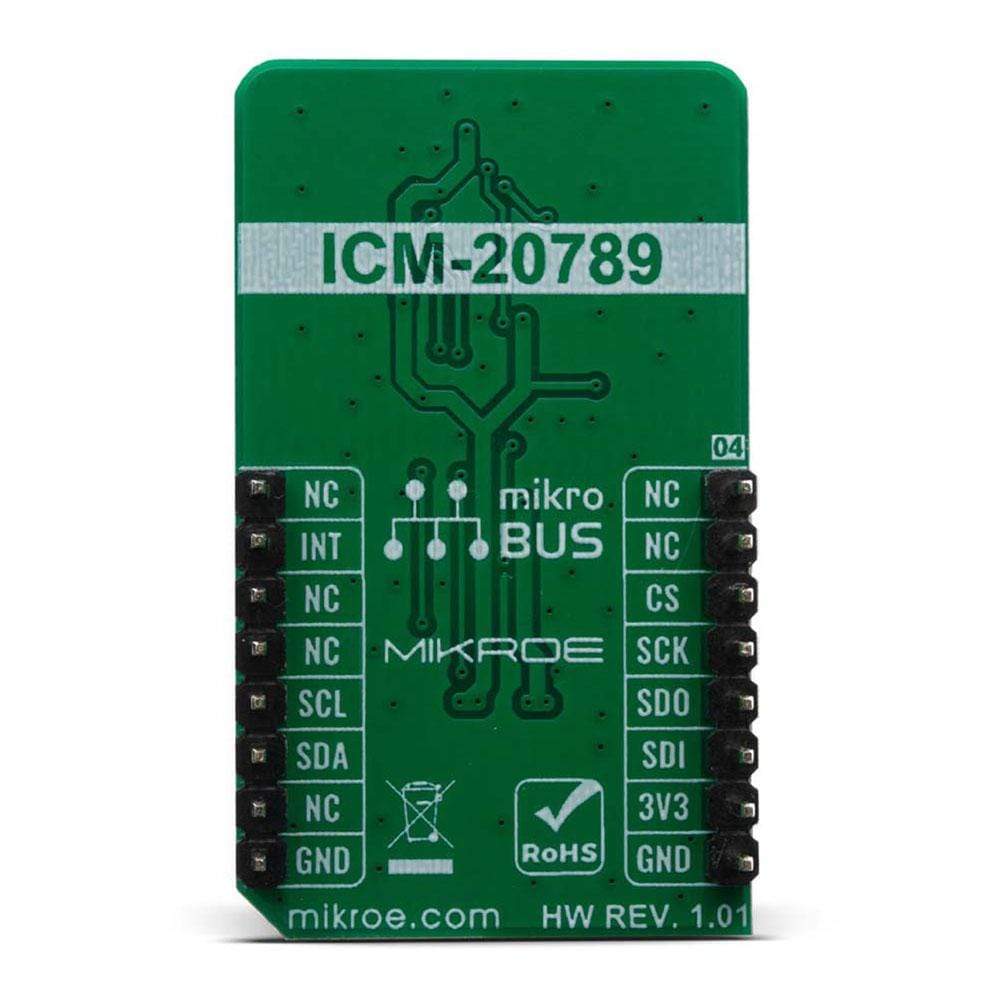
This table shows how the pinout on 6DOF IMU 5 Click corresponds to the pinout on the mikroBUS™ socket (the latter shown in the two middle columns).
Notes | Pin | Pin | Notes | ||||
---|---|---|---|---|---|---|---|
NC | 1 | AN | PWM | 16 | NC | ||
NC | 2 | RST | INT | 15 | INT | Interrupt | |
SPI Chip Select | CS | 3 | CS | RX | 14 | NC | |
SPI Clock | SCK | 4 | SCK | TX | 13 | NC | |
SPI Data OUT | SDO | 5 | MISO | SCL | 12 | SCL | I2C Clock |
SPI Data IN | SDI | 6 | MOSI | SDA | 11 | SDA | I2C Data |
Power Supply | 3.3V | 7 | 3.3V | 5V | 10 | NC | |
Ground | GND | 8 | GND | GND | 9 | GND | Ground |
Onboard settings and indicators
Label | Name | Default | Description |
---|---|---|---|
LD1 | PWR | - | Power LED Indicator |
6DOF IMU 5 Click electrical specifications
Description | Min | Typ | Max | Unit |
---|---|---|---|---|
Supply Voltage | -0.3 | 3.3 | 6 | V |
Acceleration (Any Axis, unpowered, for 0.2ms) | - | - | 1000 | g |
Overpressure | - | - | 600 | kPa |
Operating Temperature Range | -40 | - | 85 | °C |
We provide a library for the 6DOF IMU 5 Click on our LibStock page, as well as a demo application (example), developed using MikroElektronika compilers. The demo can run on all the main MikroElektronika development boards.
Library Description
The library covers all the necessary functions that enables the usage of the 6DOF IMU 5 Click board. It initializes and defines the SPI and I2C bus drivers and drivers that offer a plethora of settings. The library also offers functions that allow reading of accelerometer,gyroscope pressure and temperature, as well as generic read and write function that offer reading( and writing ) of different lenghts of data.
Key Functions
float *z_ang_rte );
- Function is used to calculate angular rate.float *z_accel_rte );
- Function is used to calculate acceleration rate.float *temperature );
- Function processes raw data in order to get presure (in Pascals) and temperature(in degree Centigrade).
Example Description
The application is composed of three sections :
- System Initialization - Initializes SPI and I2C modules, LOG and GPIO structures, sets INT pin as input.
- Application Initialization - Initalizes SPI and I2C drivers, performs safety check, applies default and barometer setups and writes an initial log.
- Application Task - (code snippet) Demonstrates use of 6DOF IMU 5 click board by reading angular rate, acceleration rate and pressure and temperature from on sensor barometer and displaying data via USART terminal.
void application_task ( ) { c6dofimu5_angular_rate( &x_gyro, &y_gyro, &z_gyro ); mikrobus_logWrite( "Angular rate: ", _LOG_LINE ); FloatToStr( x_gyro, log_txt ); mikrobus_logWrite( "X-axis: ", _LOG_TEXT ); Ltrim( log_txt ); mikrobus_logWrite( log_txt, _LOG_LINE ); FloatToStr( y_gyro, log_txt ); mikrobus_logWrite( "Y-axis: ", _LOG_TEXT ); Ltrim( log_txt ); mikrobus_logWrite( log_txt, _LOG_LINE ); FloatToStr( z_gyro, log_txt ); mikrobus_logWrite( "Z-axis: ", _LOG_TEXT ); Ltrim( log_txt ); mikrobus_logWrite( log_txt, _LOG_LINE ); mikrobus_logWrite( "---------------------", _LOG_LINE ); c6dofimu5_acceleration_rate( &x_accel, &y_accel, &z_accel ); mikrobus_logWrite( "Acceleration rate: ", _LOG_LINE ); FloatToStr( x_accel, log_txt ); mikrobus_logWrite( "X-axis: ", _LOG_TEXT ); Ltrim( log_txt ); mikrobus_logWrite( log_txt, _LOG_LINE ); FloatToStr( y_accel, log_txt ); mikrobus_logWrite( "Y-axis: ", _LOG_TEXT ); Ltrim( log_txt ); mikrobus_logWrite( log_txt, _LOG_LINE ); FloatToStr( z_accel, log_txt ); mikrobus_logWrite( "Z-axis: ", _LOG_TEXT ); Ltrim( log_txt ); mikrobus_logWrite( log_txt, _LOG_LINE ); mikrobus_logWrite( "---------------------", _LOG_LINE ); c6dofimu5_read_raw_data( &raw_pres, &raw_temp ); c6dofimu5_process_data ( raw_pres, raw_temp, &pressure, &temperature ); FloatToStr( pressure, log_txt ); mikrobus_logWrite( "Pressure: ", _LOG_TEXT ); Ltrim( log_txt ); mikrobus_logWrite( log_txt, _LOG_LINE ); FloatToStr( temperature, log_txt ); mikrobus_logWrite( "Temperature: ", _LOG_TEXT ); Ltrim( log_txt ); mikrobus_logWrite( log_txt, _LOG_LINE ); mikrobus_logWrite( "---------------------", _LOG_LINE ); mikrobus_logWrite( "", _LOG_LINE ); mikrobus_logWrite( "---------------------", _LOG_LINE ); Delay_ms( 1000 ); }
The full application code, and ready to use projects can be found on our LibStock page.
Other mikroE Libraries used in the example:
- I2C
- SPI
- UART
- Conversions
Additional Notes and Information
Depending on the development board you are using, you may need USB UART click, USB UART 2 click or RS232 click to connect to your PC, for development systems with no UART to USB interface available on the board. The terminal available in all MikroElektronika compilers, or any other terminal application of your choice, can be used to read the message.
mikroSDK
This Click board™ is supported with mikroSDK - MikroElektronika Software Development Kit. To ensure proper operation of mikroSDK compliant Click board™ demo applications, mikroSDK should be downloaded from the LibStock and installed for the compiler you are using.
Frequently Asked Questions
Have a Question?
Be the first to ask a question about this.