


Mikroelektronika d.o.o.
AD-SWIO Click-Platine
AD-SWIO Click-Platine
SKU: MIKROE-4081
Verfügbarkeit für Abholungen konnte nicht geladen werden


Overview
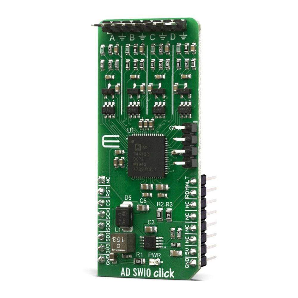
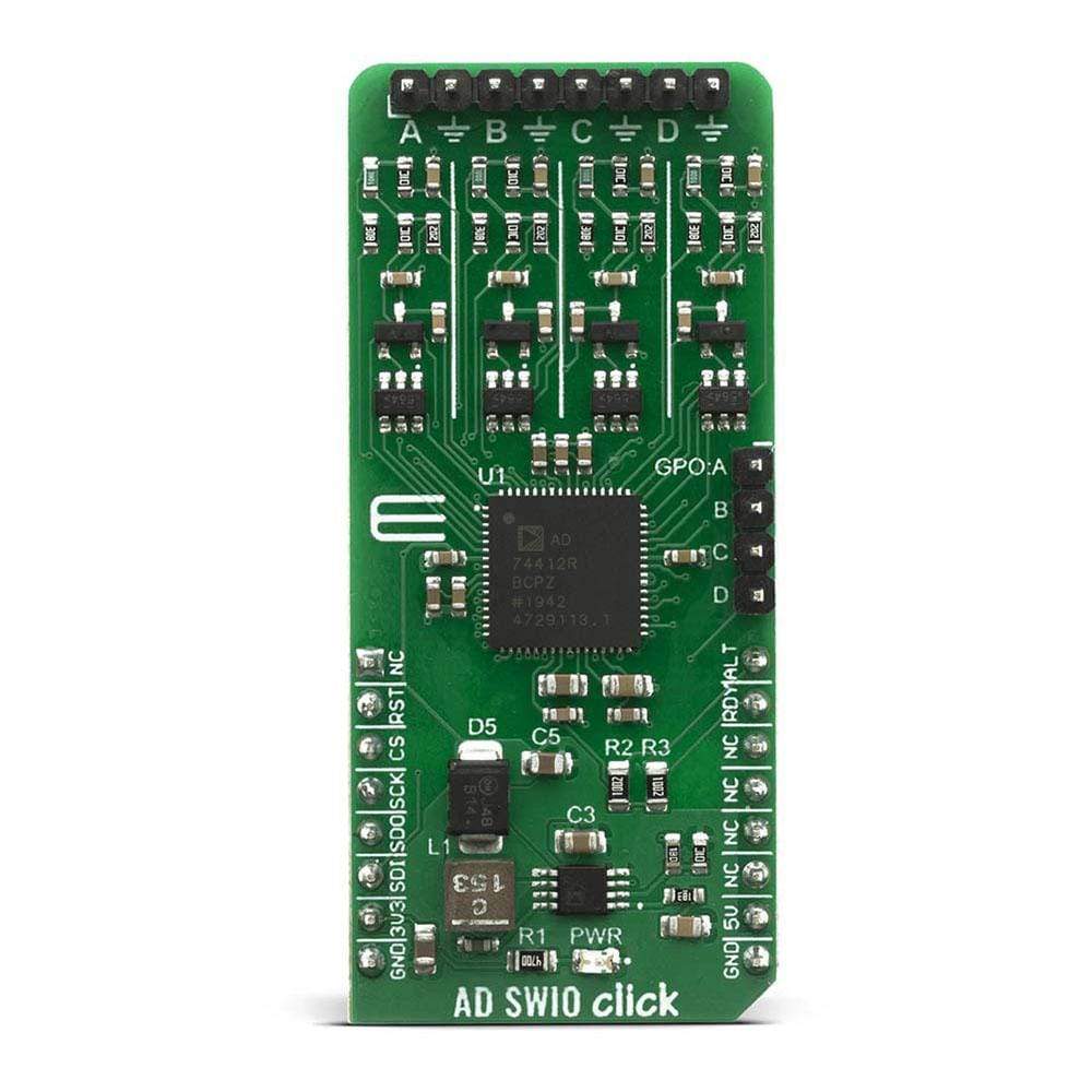
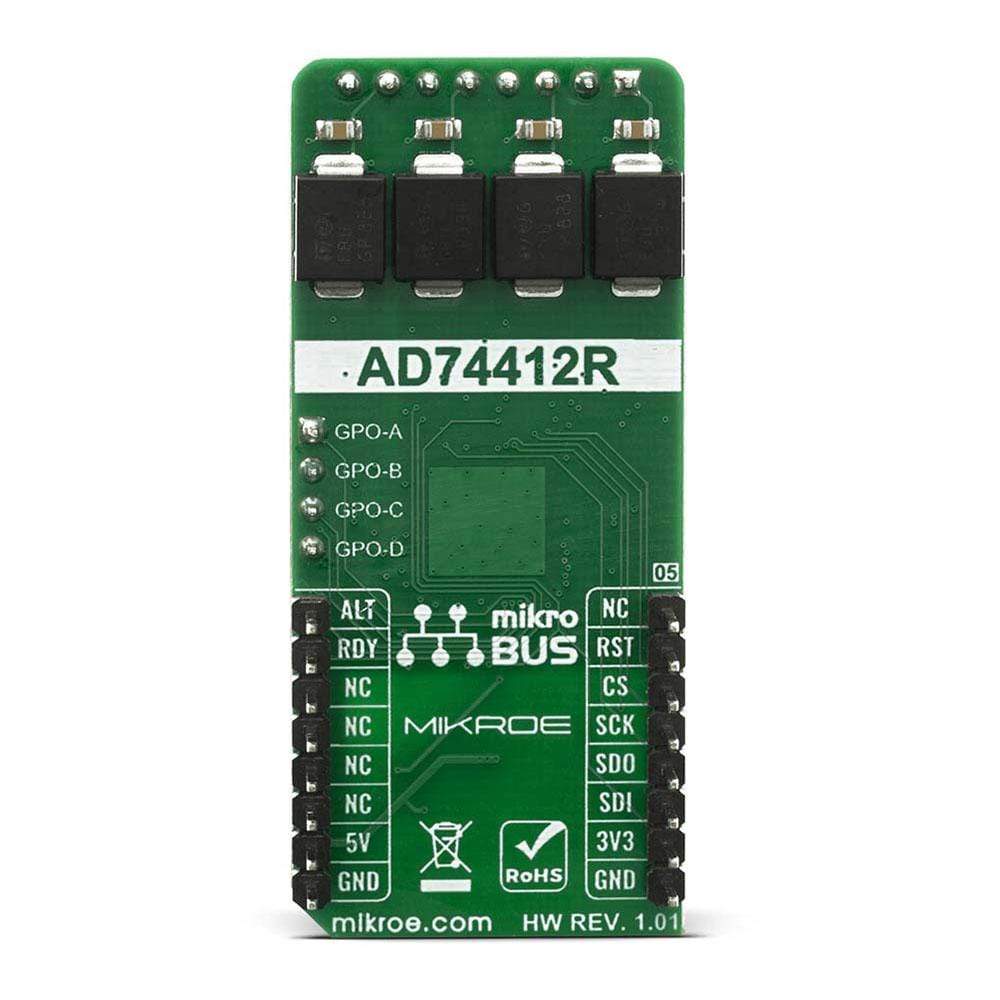
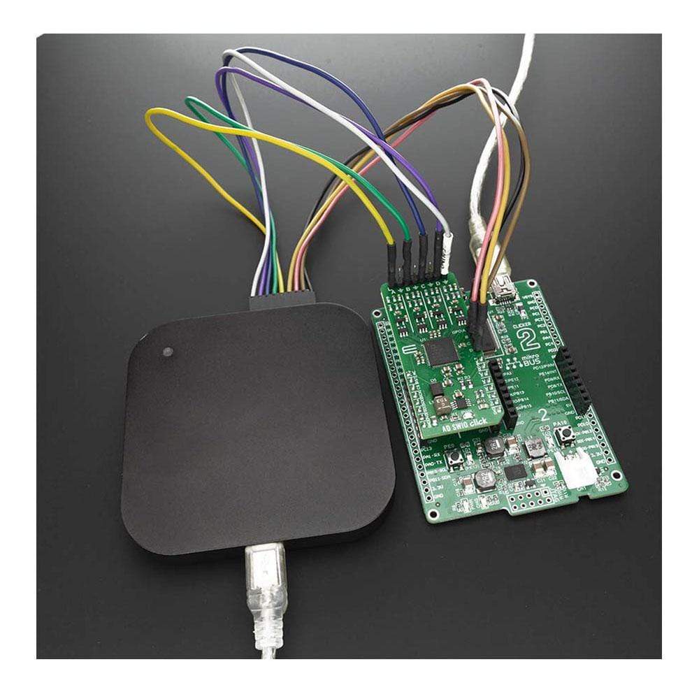
The AD-SWIO Click Board™ is a quad-channel software-configurable input/output solution based on AD74412R. The AD74412R is a quad-channel software-configurable input/output integrated circuit for building and process control applications. The device provides a fully integrated single-chip solution for input and output operation.
The AD-SWIO Click Board™ contains four 13-bit DACs, one per chanal, and 16-bit Σ-∆ ADC. These options give a lot of flexibility in choosing functionality for analogue output, analogue input, digital input, resistance temperature detector (RTD), and thermocouple measurements integrated into a single chip solution with a serial peripheral interface (SPI).
Downloads
Das AD-SWIO Click Board™ ist eine softwarekonfigurierbare Vierkanal-Ein-/Ausgabelösung auf Basis von AD74412R. AD74412R ist ein softwarekonfigurierbarer Vierkanal-Ein-/Ausgabe-integrierter Schaltkreis für Gebäude- und Prozesssteuerungsanwendungen. Das Gerät bietet eine vollständig integrierte Einzelchiplösung für den Ein- und Ausgabebetrieb.
Das AD-SWIO Click Board™ enthält vier 13-Bit-DACs, einen pro Kanal, und einen 16-Bit-Σ-∆-ADC. Diese Optionen bieten viel Flexibilität bei der Auswahl der Funktionalität für analogen Ausgang, analogen Eingang, digitalen Eingang, Widerstandstemperaturdetektor (RTD) und Thermoelementmessungen, integriert in eine Einzelchip-Lösung mit einer seriellen Peripherieschnittstelle (SPI).
| General Information | |
|---|---|
Part Number (SKU) |
MIKROE-4081
|
Manufacturer |
|
| Physical and Mechanical | |
Weight |
0.02 kg
|
| Other | |
EAN |
8606018717262
|
Frequently Asked Questions
Have a Question?
Be the first to ask a question about this.