


Mikroelektronika d.o.o.
Motion 2 Click-Board - Konsolentisch
Motion 2 Click-Board - Konsolentisch
SKU: MIKROE-4059
Verfügbarkeit für Abholungen konnte nicht geladen werden


Overview
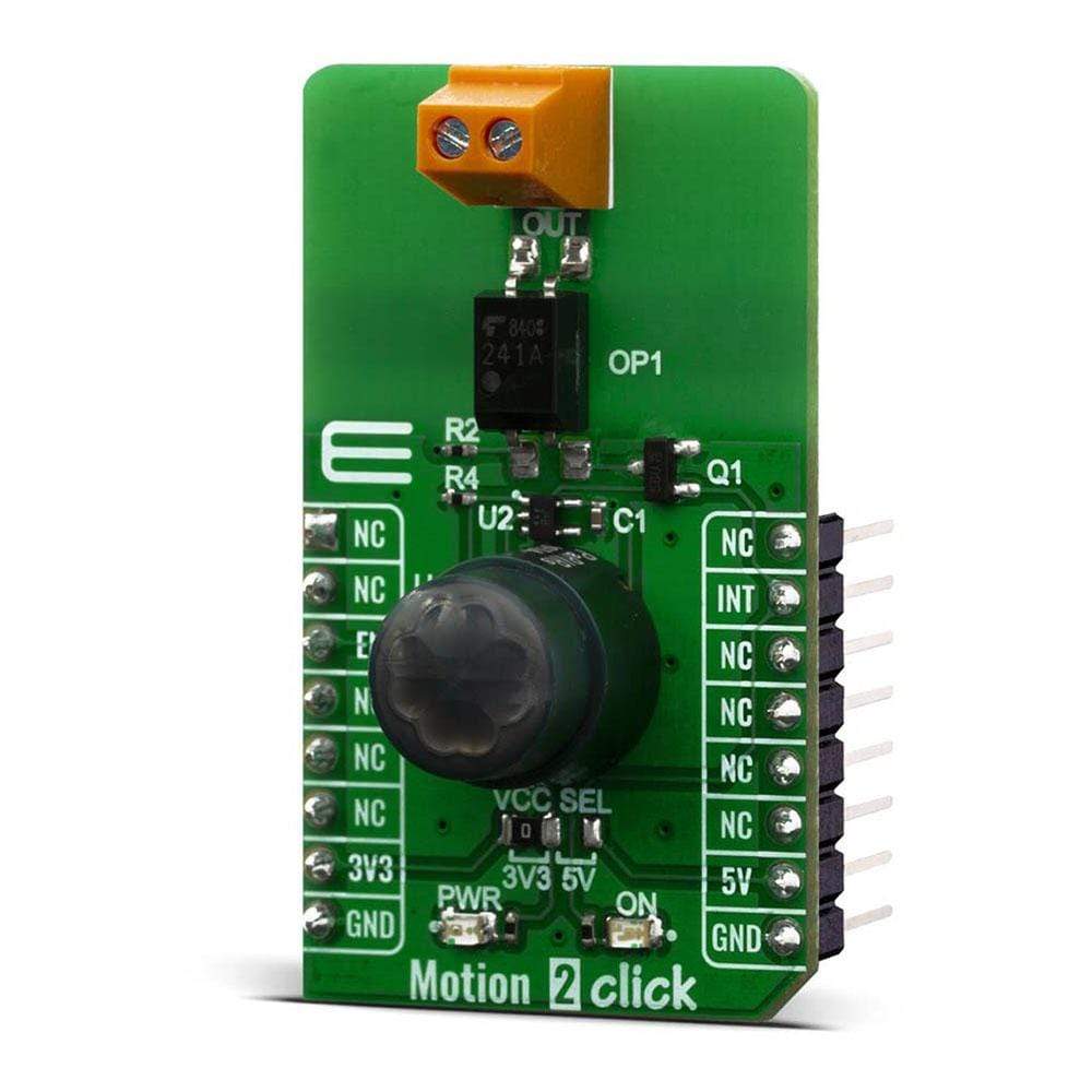
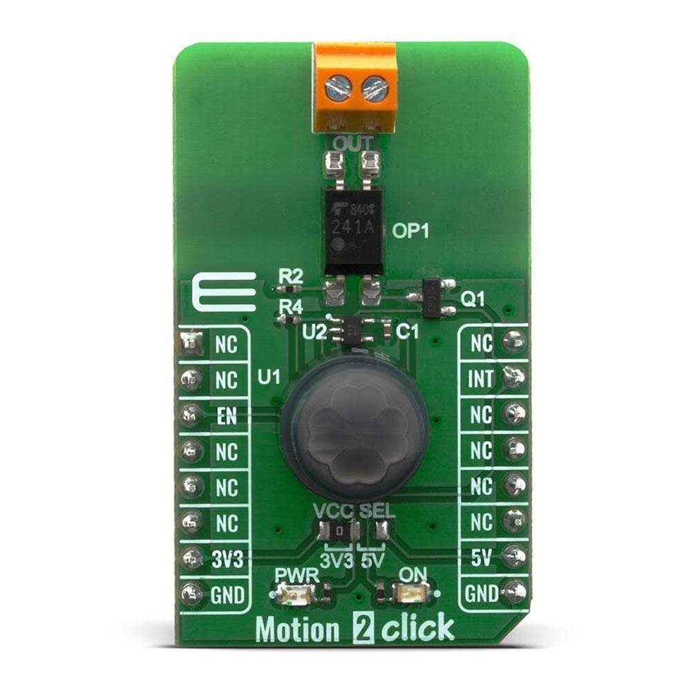
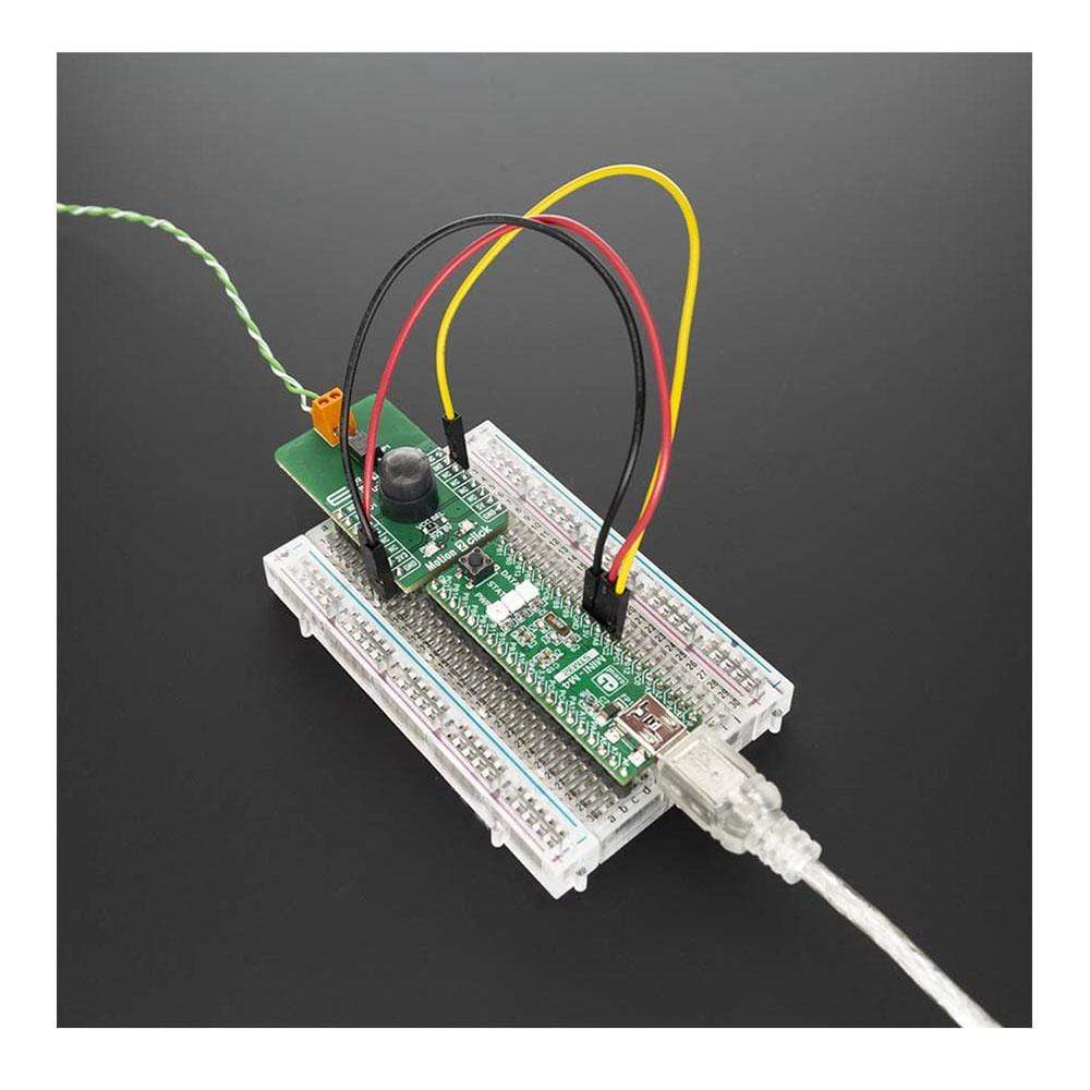
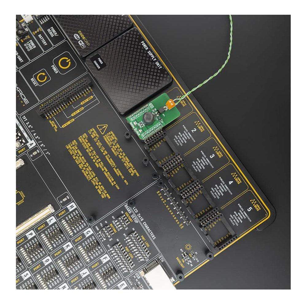
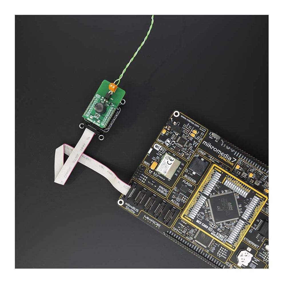
the The Motion 2 Click Board™ is based on the EKMC1607112, PIR motion sensor from Panasonic Corporation that's used as a human motion detector. Also featured on Motion 2 Click Board™ is TLP241A photo relay from Toshiba that is used to provide reinforced galvanic isolation for the external signals used to drive some external high power electronic equipment when motion is detected. It's allowing up to 40V between the SSR contacts in the OFF state, and currents up to 2A while in the ON state, thanks to a very low ON-state resistance.
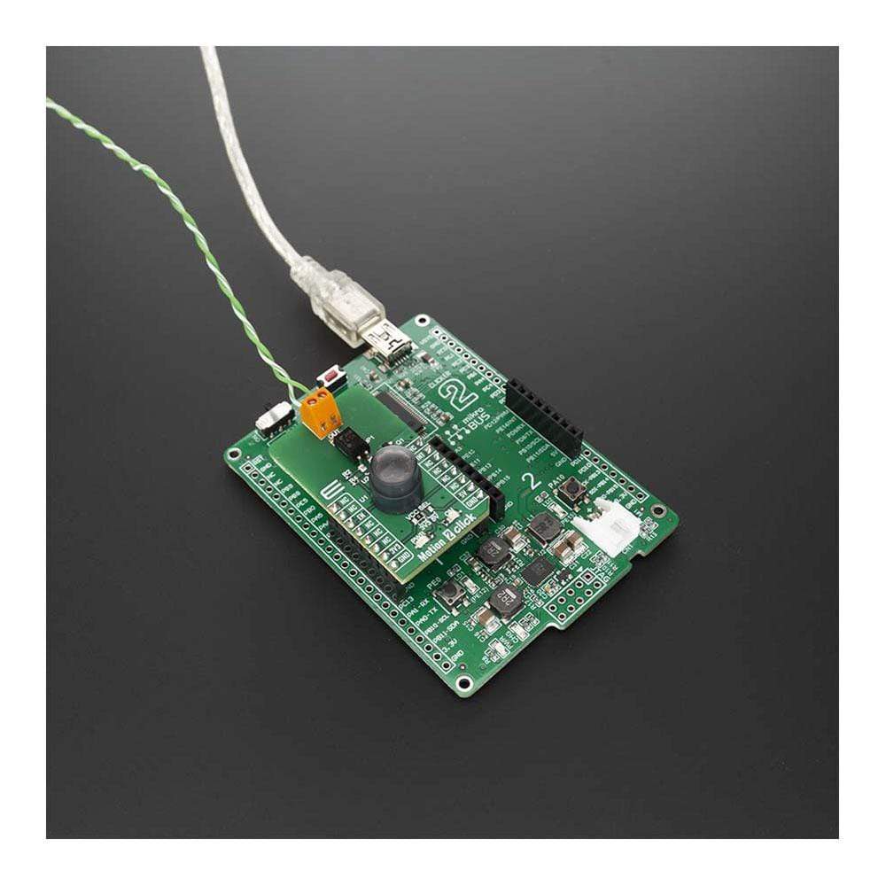
The Motion 2 Click Board™ is supported by a mikroSDK compliant library, which includes functions that simplify software development. This Click Board™ comes as a fully tested product, ready to be used on a system equipped with the mikroBUS™ socket.
Downloads
Das Motion 2 Click Board™ ist basiert auf dem EKMC1607112, einem PIR-Bewegungssensor von Panasonic Corporation, der als Bewegungsmelder für Personen verwendet wird. Ebenfalls auf dem Motion 2 Click Board™ enthalten ist das TLP241A-Fotorelais von Toshiba, das für eine verstärkte galvanische Trennung der externen Signale sorgt, die zum Ansteuern einiger externer elektronischer Hochleistungsgeräte verwendet werden, wenn eine Bewegung erkannt wird. Dank eines sehr geringen Widerstands im eingeschalteten Zustand sind im ausgeschalteten Zustand bis zu 40 V zwischen den SSR-Kontakten und im eingeschalteten Zustand Ströme von bis zu 2 A möglich.
Das Motion 2 Click Board™ wird von einer mikroSDK-kompatiblen Bibliothek unterstützt, die Funktionen enthält, die die Softwareentwicklung vereinfachen. Dieses Click Board™ wird als vollständig getestetes Produkt geliefert und ist bereit für den Einsatz auf einem System, das mit der mikroBUS™-Buchse ausgestattet ist.
| General Information | |
|---|---|
Part Number (SKU) |
MIKROE-4059
|
Manufacturer |
|
| Physical and Mechanical | |
Weight |
0.02 kg
|
| Other | |
EAN |
8606018717163
|
Frequently Asked Questions
Have a Question?
Be the first to ask a question about this.