


Mikroelektronika d.o.o.
Balancer 2 Click-Platine
Balancer 2 Click-Platine
SKU: MIKROE-4058
Verfügbarkeit für Abholungen konnte nicht geladen werden


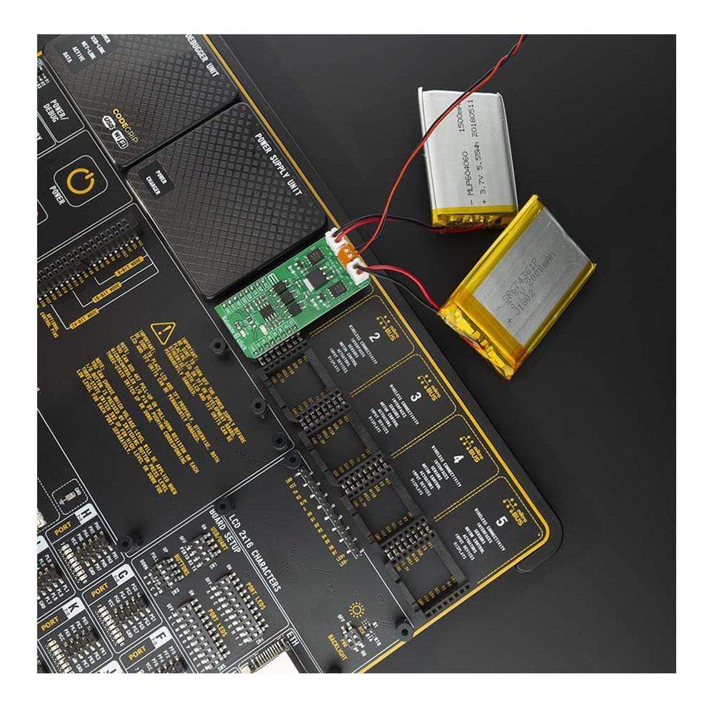

Overview
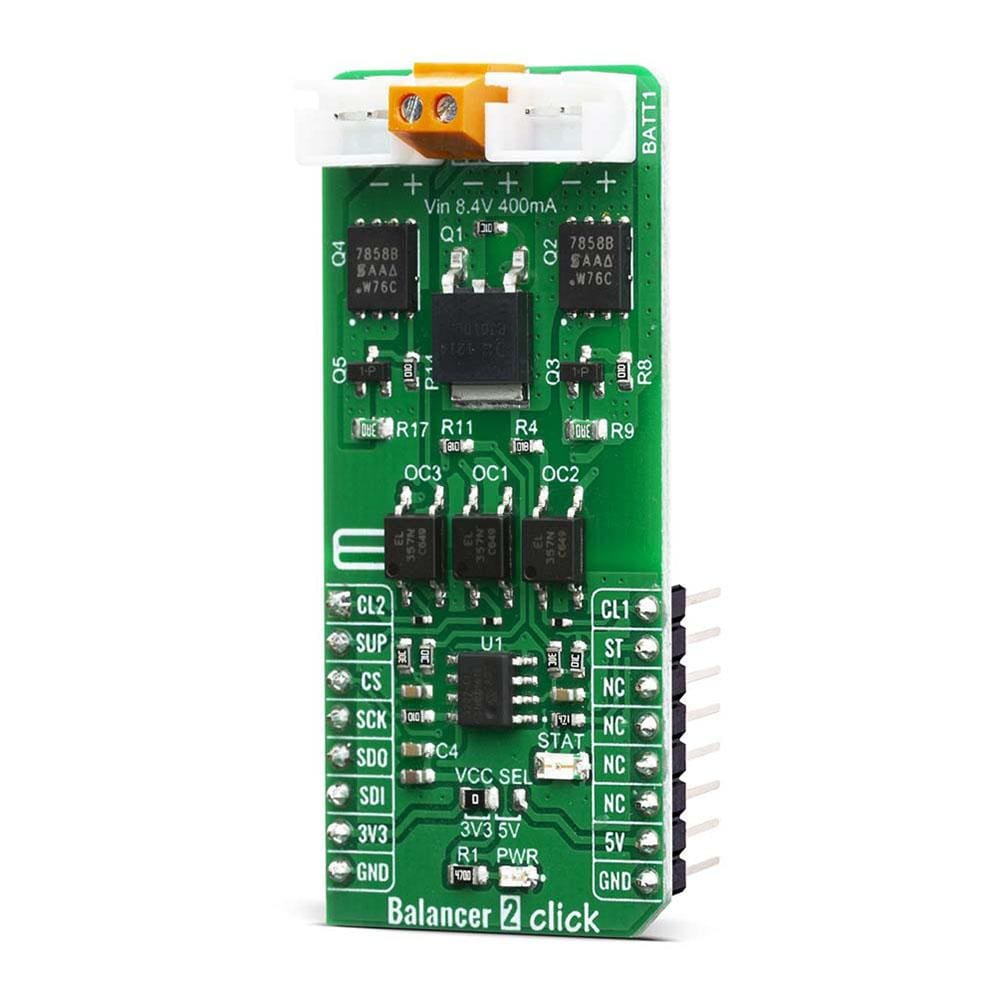
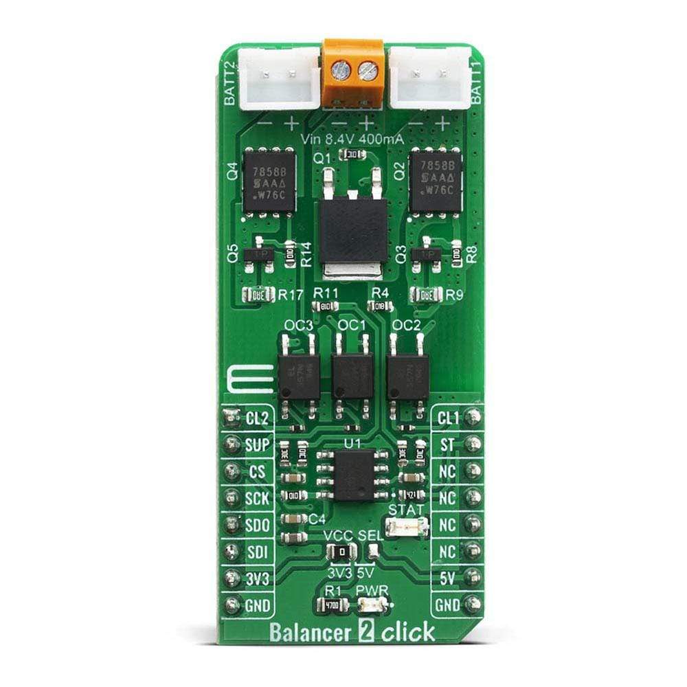
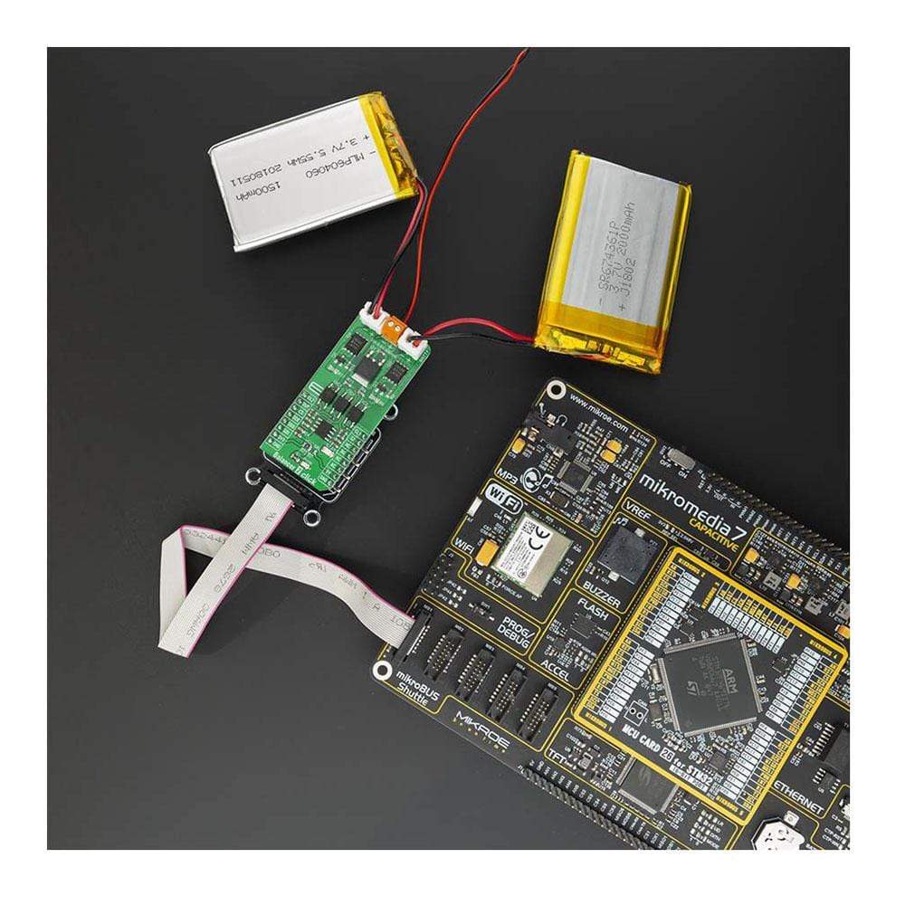
The Balancer 2 Click Board™ is an overvoltage protection device for a 2-series cell lithium-ion battery. Click contains two separate overvoltage battery detection circuits and automatic cell imbalance correction. It can be used for various applications, power tools, portable equipment, and instrumentation, to energy storage systems (ESS), while providing the output voltage at the same time. By utilizing an externally connected power supply, it can charge 2-cell Li-Ion batteries.
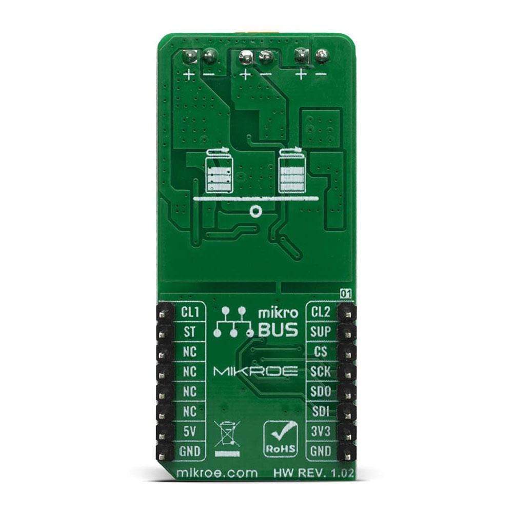
The Balancer 2 Click Board™ is supported by the mikroSDK compliant library, which includes functions that simplify software development. The Click Board™ comes as a fully tested product, ready to be used on a system equipped with mikroBUS™.
Downloads
Das Balancer 2 Click Board™ ist ein Überspannungsschutzgerät für eine Lithium-Ionen-Batterie mit 2 Serienzellen. Click enthält zwei separate Überspannungserkennungsschaltkreise für Batterien und eine automatische Korrektur der Zellunwucht. Es kann für verschiedene Anwendungen, Elektrowerkzeuge, tragbare Geräte und Instrumente bis hin zu Energiespeichersystemen (ESS) verwendet werden und liefert gleichzeitig die Ausgangsspannung. Durch Verwendung eines extern angeschlossenen Netzteils kann es 2-Zellen-Li-Ionen-Batterien laden.
Das Balancer 2 Click Board™ wird von der mikroSDK-kompatiblen Bibliothek unterstützt, die Funktionen enthält, die die Softwareentwicklung vereinfachen. Das Click Board™ wird als vollständig getestetes Produkt geliefert und ist bereit für den Einsatz auf einem mit mikroBUS™ ausgestatteten System.
| General Information | |
|---|---|
Part Number (SKU) |
MIKROE-4058
|
Manufacturer |
|
| Physical and Mechanical | |
Weight |
0.022 kg
|
| Other | |
EAN |
8606018717156
|
Frequently Asked Questions
Have a Question?
Be the first to ask a question about this.