Heizungs-Click-Platine
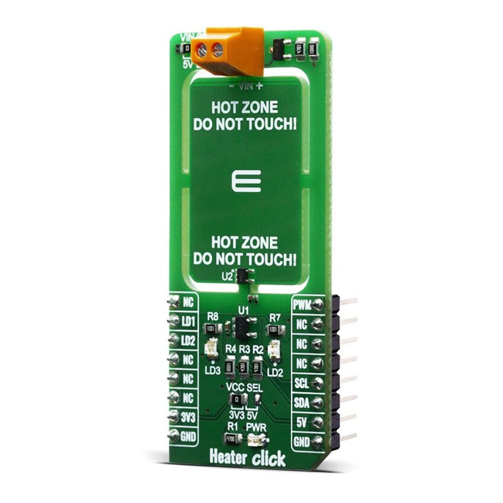
Das Heater Click Board™ wurde zum Testen von PCB-Heizkonzepten entwickelt und ist ein nützliches Werkzeug zum Heizen kompletter Gehäuse, bei denen es entscheidend ist, in einem bestimmten Temperaturbereich zu bleiben. Die genaue PCB-Temperatur kann mit einem integrierten Temperatursensor TMP235 von Texas Instruments eingestellt und gesteuert werden. Heater Click ist ein nützliches Werkzeug für einige Projekte und Produkte, die eine Art von Heizung benötigen, sei es, um zu verhindern, dass Elektronik zu kalt wird, um die Luftfeuchtigkeit zu kontrollieren, um eine Substanz zu erhitzen oder sogar um zu verhindern, dass ein Material an einem anderen klebt.
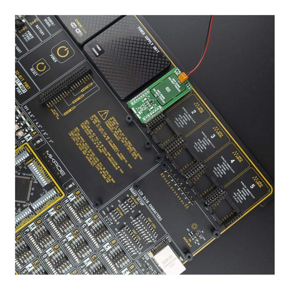
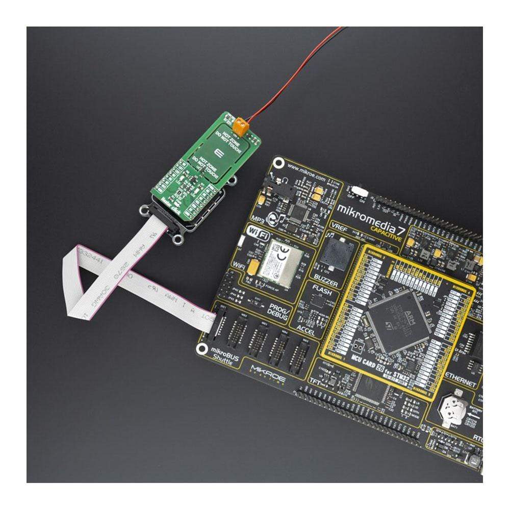
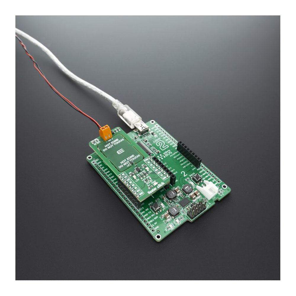
Das Heater Click Board™ wird von einer mikroSDK-kompatiblen Bibliothek unterstützt, die Funktionen enthält, die die Softwareentwicklung vereinfachen. Dieses Click Board™ wird als vollständig getestetes Produkt geliefert und ist bereit für den Einsatz auf einem System, das mit der mikroBUS™-Buchse ausgestattet ist.
How Does The Heater Click Board™ Work?
The Heater Click Board™ works on a principle of Joule heating, also known as resistance heating (resistive heating), a process by which the passage of an electric current through a conductor produces heat. Energy dissipated per unit time is equal to current passing through resistor times electric potential difference.
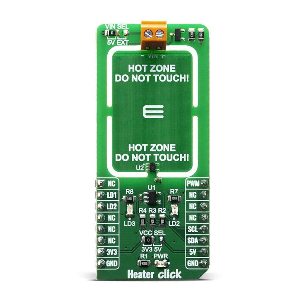
The Heater Click Board™ allows PCB temperature adjusting and monitoring as it have embedded trace resistor on top layer of PCB. Resistor is made from copper 1oz thick and a pattern of 0.1mm wide track 1950mm long, this give us about 10 ohm resistance at 25 degrees Celsius.
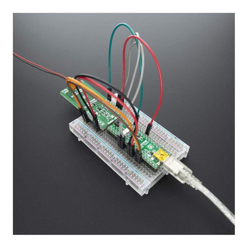
With on board VIN SEL jumper power supply can be selected as 5V from mikroBUS or any other voltage from external power supply at terminal block VIN. Using mikroBUS PWM pin power dissipation can be adjusted and therfore temperature controlled.
Heater Click minimize temperature spread from embedded resistor by having PCB gaps between it and rest of the click bord and components, by doing so hot zone is easier to warm up and keeping it at exact temperature without affecting rest of the commponents. LEDs are connected to LD1 and LD2 GPIO pins and can be used for example to signal user if temperature is ramping up or achieved, or any other user defined signaling.
Since the temperature rise in a heater is a function of its resistance and voltage, you don't always need to design a heater from scratch. So long as you can apply a specific voltage, you should be able to achieve your desired temperature and monitoring it through I2C.
Temperature is monitored with TMP235 precision CMOS integrated-circuit linear analog temperature sensor with an output voltage proportional to temperature, The TMP235 device provides a positive slope output of 10 mV/°C over the full –40°C to +150°C temperature range. Using MCP3221 a 12-bit ADC, output voltage from temperature sensor can be red through I2C. Communication to the MCP3221 is performed using a 2-wire, I2C compatible interface. Standard (100 kHz) and Fast (400 kHz) I2C modes are available with the device.
SPECIFICATIONS
Type | Temperature |
Applications | Seed germination, 3D printer heated beds, humidity control, loads, heater reference |
On-board modules | MCP3221, TMP235 |
Key Features | Stable temperature adjusting and monitoring |
Interface | I2C,PWM |
Compatibility | mikroBUS |
Click board size | L (57.15 x 25.4 mm) |
Input Voltage | 3.3V or 5V |
PINOUT DIAGRAM
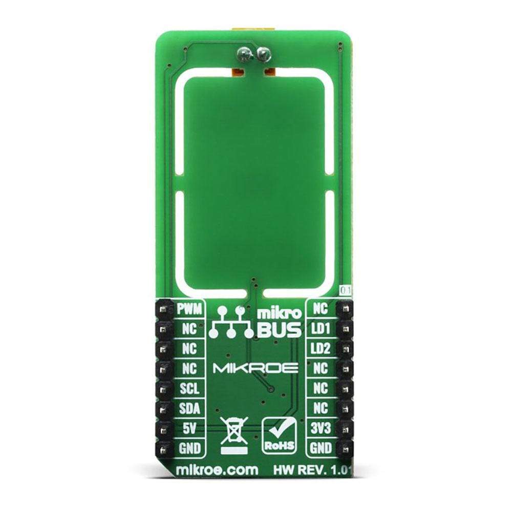
This table shows how the pinout of the Heater Click Board™ corresponds to the pinout on the mikroBUS™ socket (the latter shown in the two middle columns).
Notes | Pin | Pin | Notes | ||||
---|---|---|---|---|---|---|---|
NC | 1 | AN | PWM | 16 | PWM | Pulse width modulation | |
Red Led | LD1 | 2 | RST | INT | 15 | NC | |
Blue Led | LD2 | 3 | CS | RX | 14 | NC | |
NC | 4 | SCK | TX | 13 | NC | ||
NC | 5 | MISO | SCL | 12 | SCL | I2C Clock | |
NC | 6 | MOSI | SDA | 11 | SDA | I2C Data | |
Power Supply | 3.3V | 7 | 3.3V | 5V | 10 | 5V | Power supply |
Ground | GND | 8 | GND | GND | 9 | GND | Ground |
ONBOARD SETTINGS AND INDICATORS
Label | Name | Default | Description |
---|---|---|---|
PWR | Green Led | - | Power LED Indicator |
LD2 | Red Led | - | Red LED Indicator |
LD3 | Blue Led | - | Blue LED Indicator |
Software Support
We provide a library for the Heater Click Board™ on our LibStock page, as well as a demo application (example), developed using MikroElektronika compilers. The demo can run on all the main MikroElektronika development boards.
Library Description
Library provides control over led pins and function for reading raw ADC data as well a function for reading converted data in temperature.
Key Functions
uint16_t heater_read_data ( void );
- Function for reading raw ADC datafloat heater_read_temp ( void );
- Function that raw data converts in temperature
Example Description
The application is composed of three sections :
- System Initialization - Initialization of I2C, UART modules and GPIO pins
- Application Initialization - Initialization of PWM module and start heating up
- Application Task - During the task, the device is heating up to 50 degree C and then cooling down to 40 degree C
void application_task ( ) { temp_read = heater_read_temp( ); if ( ( temp_read > HOT_TEMP ) && ( status_dev == HEATER_WAITING ) ) { status_dev = HEATER_COOLING; } else if ( ( temp_read < COOL_TEMP ) && ( status_dev == HEATER_WAITING ) ) { status_dev = HEATER_HEATING; } if ( status_dev == HEATER_HEATING ) { heater_pwm_start( ); heater_set_led1_status( HEATER_LED_ON ); heater_set_led2_status( HEATER_LED_OFF ); status_dev = HEATER_WAITING; } else if ( status_dev == HEATER_COOLING ) { heater_pwm_stop( ); heater_set_led1_status( HEATER_LED_OFF ); heater_set_led2_status( HEATER_LED_ON ); status_dev = HEATER_WAITING; } FloatToStr( temp_read, demo_txt ); mikrobus_logWrite( " - Temperature: ", _LOG_TEXT ); mikrobus_logWrite( demo_txt, _LOG_TEXT ); mikrobus_logWrite( log_degree, _LOG_LINE ); mikrobus_logWrite( "***************", _LOG_LINE ); Delay_ms( 1000 ); }
Note:
- Device turns red led on when heating up device and blue when cooling down
- For this example you should supply device with additional 7V
The full application code, and ready to use projects can be found on our LibStock page.
Other mikroE Libraries used in the example:
- I2C
- PWM
- UART
- Conversion
Additional Notes and Information
Depending on the development board you are using, you may need USB UART click, USB UART 2 click or RS232 click to connect to your PC, for development systems with no UART to USB interface available on the board. The terminal available in all MikroElektronika compilers, or any other terminal application of your choice, can be used to read the message.
MIKROSDK
The Heater Click Board™ is supported with mikroSDK - MikroElektronika Software Development Kit. To ensure proper operation of mikroSDK compliant Click board™ demo applications, mikroSDK should be downloaded from the LibStock and installed for the compiler you are using.
Heizungs-Click-Platine
Frequently Asked Questions
Have a Question?
Be the first to ask a question about this.