


Mikroelektronika d.o.o.
RS232 SPI Click-Platine
RS232 SPI Click-Platine
SKU: MIKROE-3912
Verfügbarkeit für Abholungen konnte nicht geladen werden


Overview
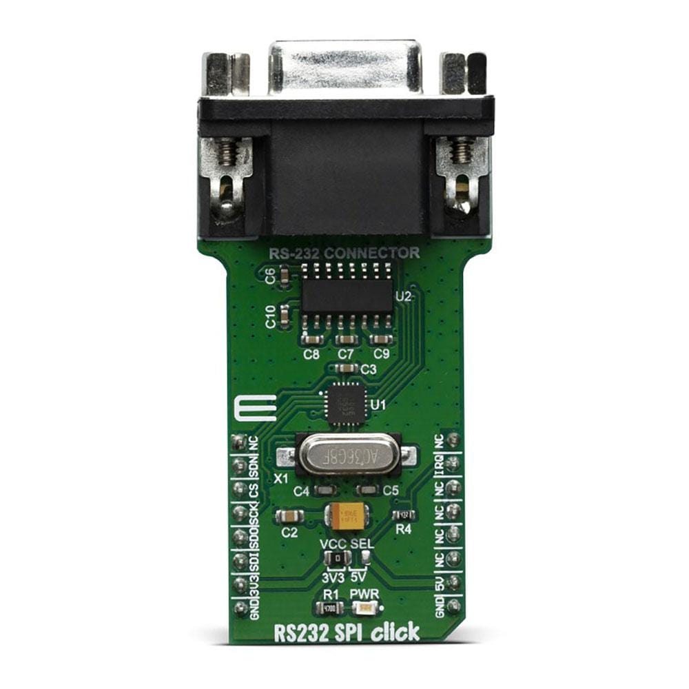
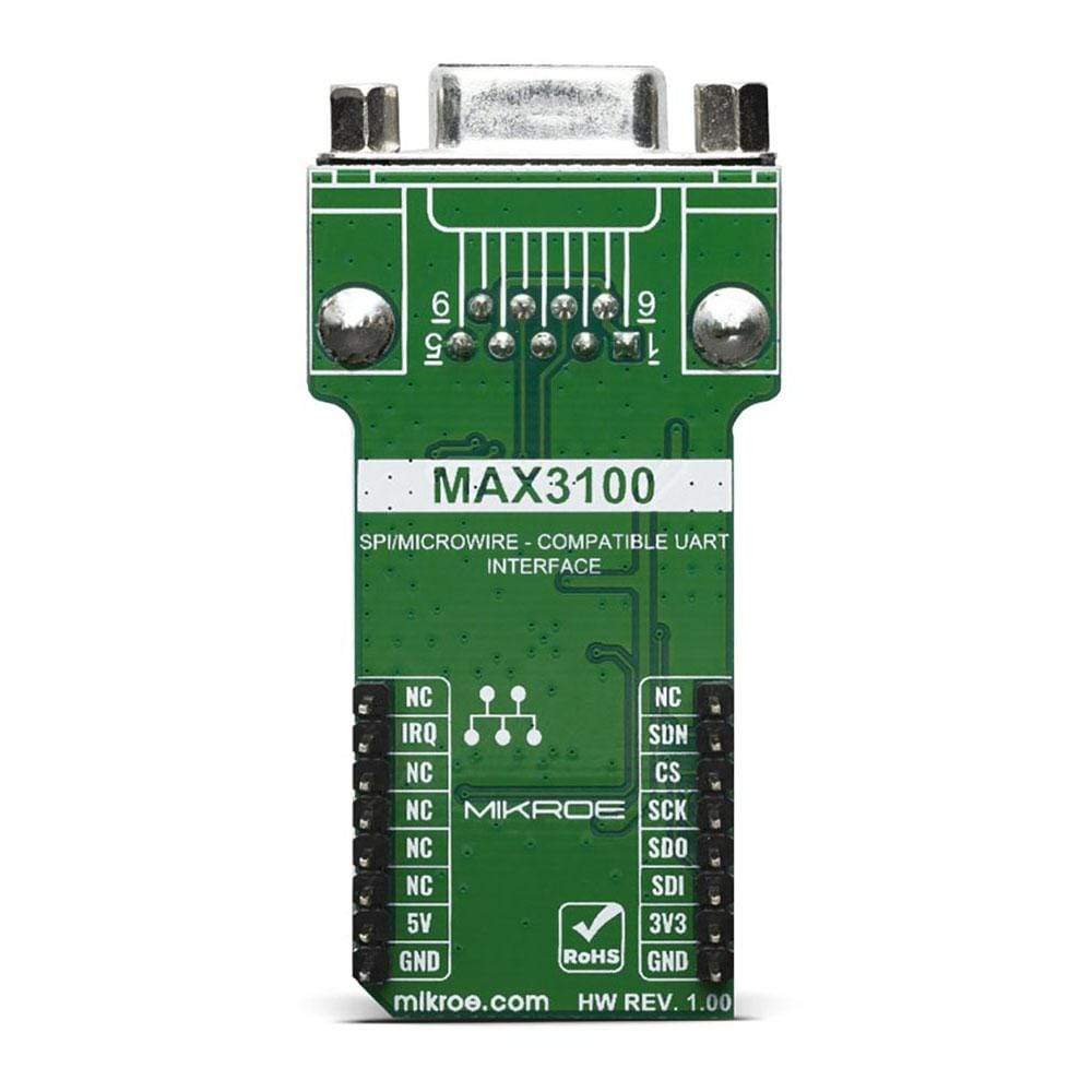
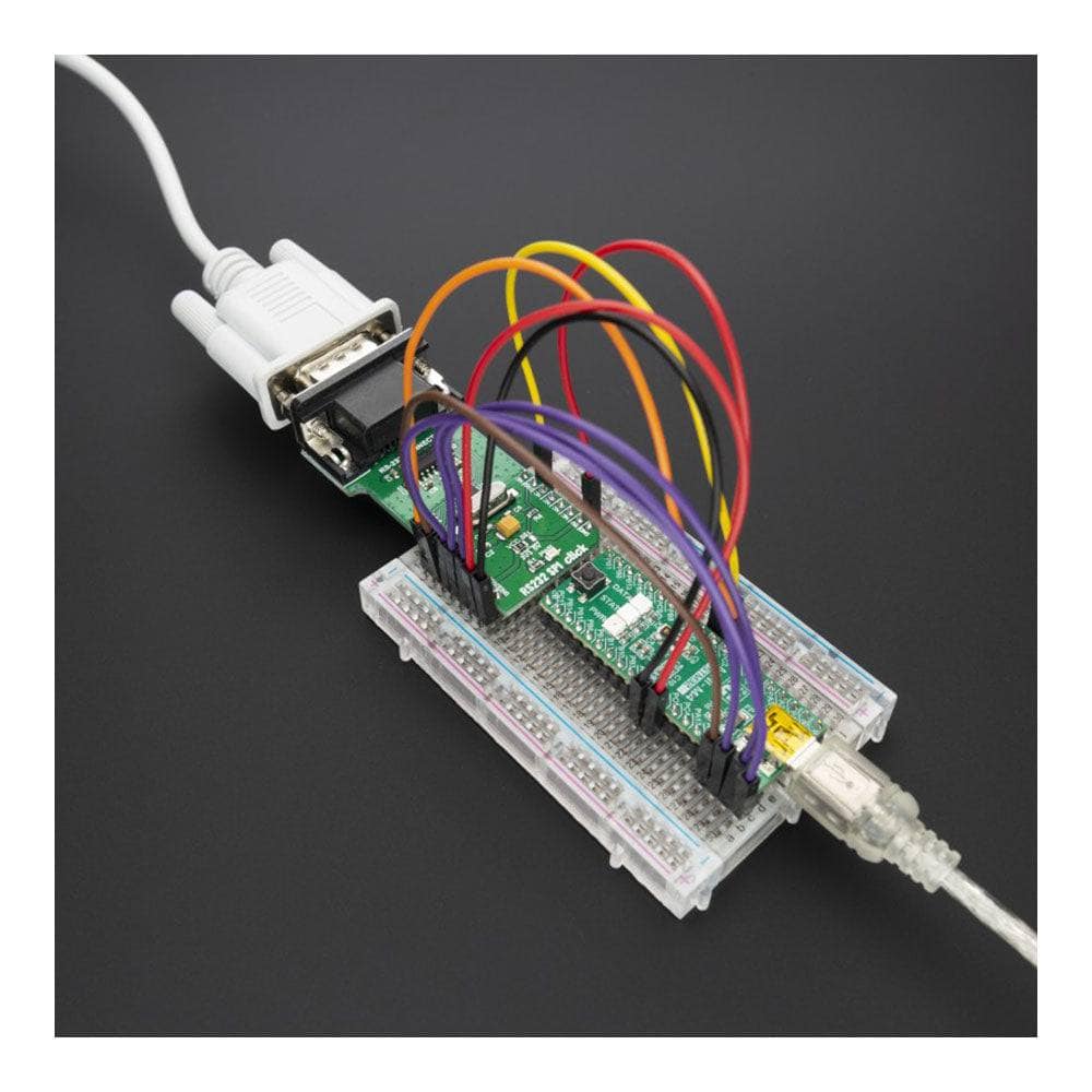
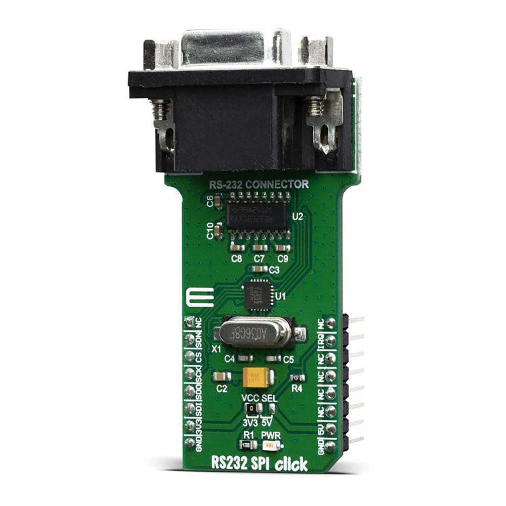
The RS232 SPI Click Board™ is based around the MAX3100, a universal asynchronous receiver transmitter (UART) - the first UART optimised explicitly for small microcontroller-based systems, from Maxim Integrated. Because of the features contained in its modules, the RS232 SPI Click Board™ can be used for handheld instruments, small networks in HVAC or Building control, UART in SPI systems, battery-powered systems, PDAs, notebooks and many more.
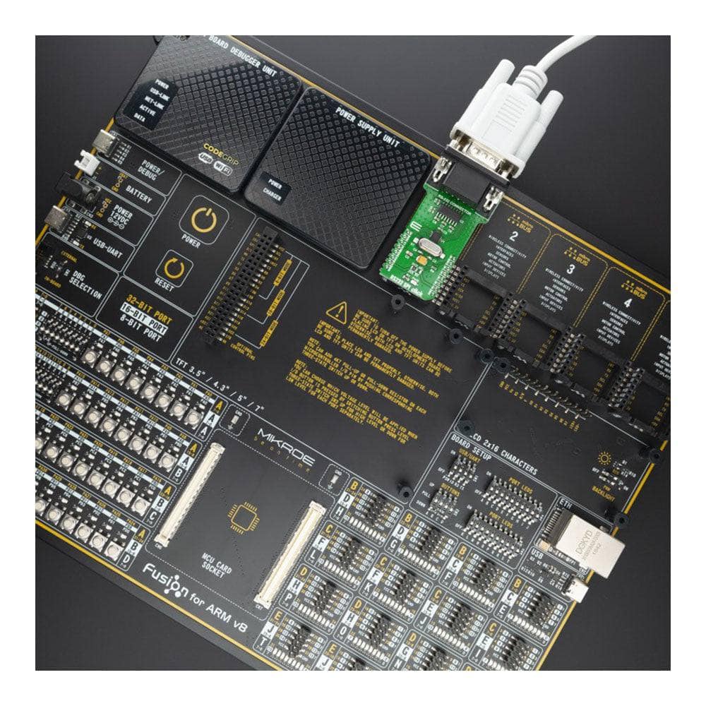
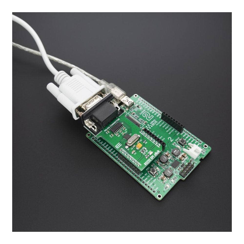
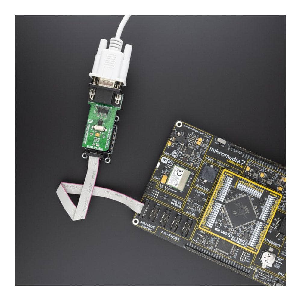
The RS232 SPI Click Board™ is supported by a mikroSDK compliant library, which includes functions that simplify software development. This Click Board™ comes as a thoroughly tested product, ready to be used on a system equipped with the mikroBUS™ socket.
Downloads
Das RS232 SPI Click Board™ basiert auf dem MAX3100, einem universellen asynchronen Empfänger-Sender (UART) – dem ersten UART, der explizit für kleine mikrocontrollerbasierte Systeme von Maxim Integrated optimiert ist. Aufgrund der in seinen Modulen enthaltenen Funktionen kann das RS232 SPI Click Board™ für tragbare Instrumente, kleine Netzwerke in der HLK- oder Gebäudesteuerung, UART in SPI-Systemen, batteriebetriebene Systeme, PDAs, Notebooks und vieles mehr verwendet werden.
Das RS232 SPI Click Board™ wird von einer mikroSDK-kompatiblen Bibliothek unterstützt, die Funktionen enthält, die die Softwareentwicklung vereinfachen. Dieses Click Board™ ist ein gründlich getestetes Produkt und kann auf einem System verwendet werden, das mit der mikroBUS™-Buchse ausgestattet ist.
| General Information | |
|---|---|
Part Number (SKU) |
MIKROE-3912
|
Manufacturer |
|
| Physical and Mechanical | |
Weight |
0.029 kg
|
| Other | |
EAN |
8606018719112
|
Frequently Asked Questions
Have a Question?
Be the first to ask a question about this.