13DOF Klick-Board
13DOF Klick-Board
Overview
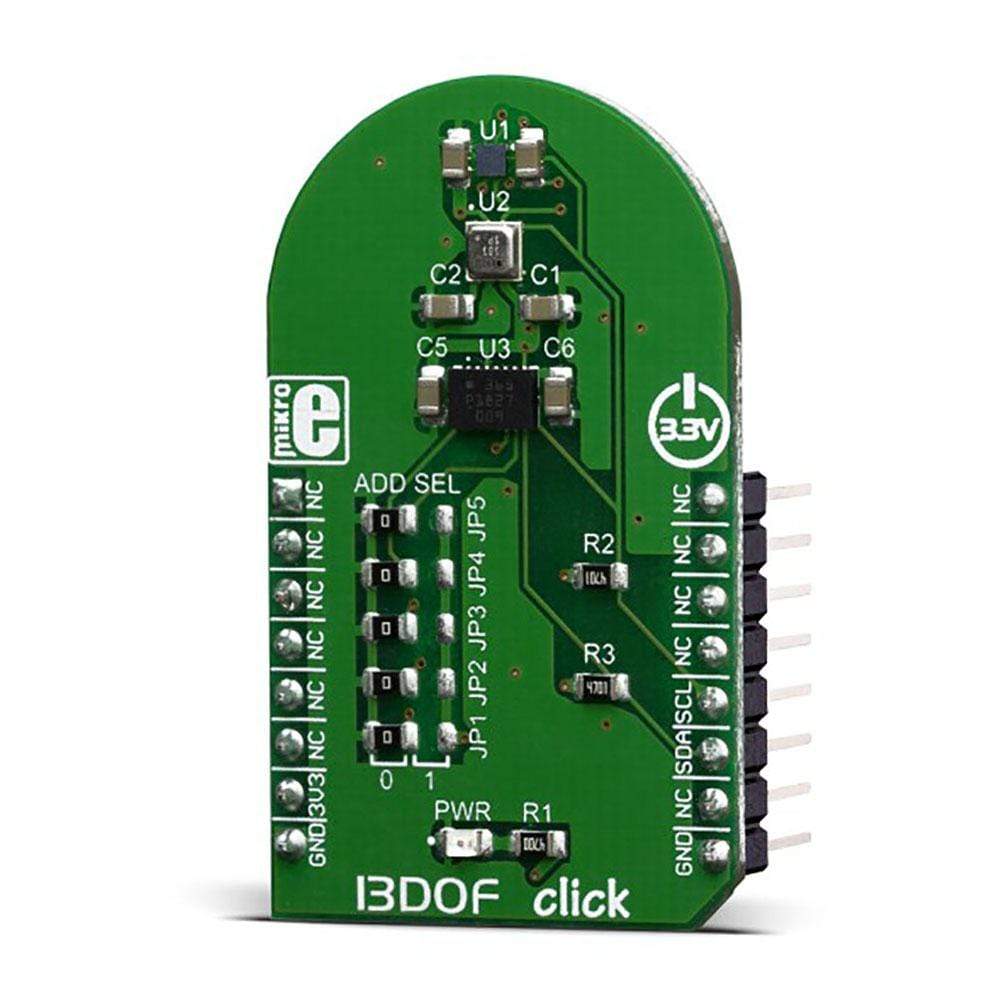
Verbessern Sie Ihre Projekte mit dem hochmodernen 13DOF Click Board. Dieses bemerkenswerte Board bringt die Bewegungsverfolgung auf ein neues Niveau an Genauigkeit und Funktionalität und eignet sich für eine breite Palette von Anwendungen, von immersivem Gaming bis hin zu präziser Navigation.
Das 13DOF Click Board integriert drei Hochleistungs-Sensor-ICs von Bosch Sensortec und sorgt so für eine außergewöhnliche Sensordatenfusion. Es verfügt über den BME680-Sensor zur digitalen Gas-, Druck-, Feuchtigkeits- und Temperaturmessung sowie den geomagnetischen BMM150-Sensor für verbesserte ortsbezogene Genauigkeit.
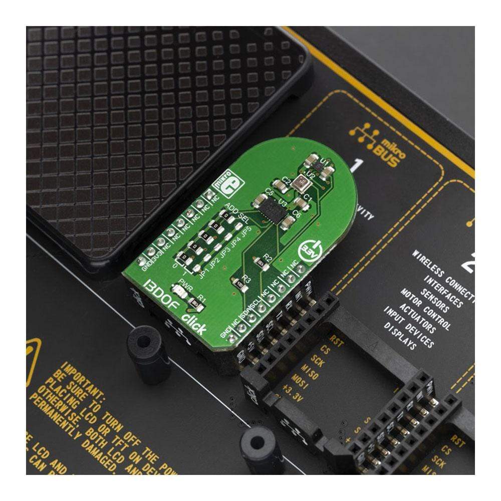
Entwickler, die an Mobiltelefonen, Smartwatches, Fitnessgeräten oder GPS-Systemen arbeiten, können sich auf das 13DOF Click Board verlassen, das eine beispiellose Präzision und Zuverlässigkeit bei der Erfassung von Sensordaten bietet. Das Board wird von einer mikroSDK-kompatiblen Bibliothek unterstützt, was die Softwareentwicklung vereinfacht. Es ist vollständig getestet und sofort einsatzbereit für Systeme mit mikroBUS-Sockel.
Bleiben Sie mit dem 13DOF Click Board in der sich schnell entwickelnden Technologielandschaft immer einen Schritt voraus. Dieses Board wurde entwickelt, um den Anforderungen moderner Technologie gerecht zu werden und bietet eine perfekte Mischung aus Genauigkeit, Leistung und Vielseitigkeit, um das Benutzererlebnis auf verschiedenen Plattformen zu verbessern.
- Außergewöhnliche Sensordatenfusion mit Bosch Sensortec ICs
- Kompatibilität mit verschiedenen Anwendungen, einschließlich Spielen und Navigation
Spezifikationen:
- Unterstützte ICs: BME680, BMM150
- Konformität: mikroSDK
The BME680 is a digital 4-in-1 sensor with gas, humidity, pressure and temperature measurement based on proven sensing principles, housed in an extremely compact metal-lid LGA package. Its small dimensions and its low power consumption enable the integration in battery-powered or frequency-coupled devices, such as handsets or wearables. The BMM150 geomagnetic sensor, a three-axis geomagnetic sensor and the BMI088 sensor module are both featured prominently and are key parts of the 13DOF Click Board™.
How Does The 13DOF Click Board™ Work?
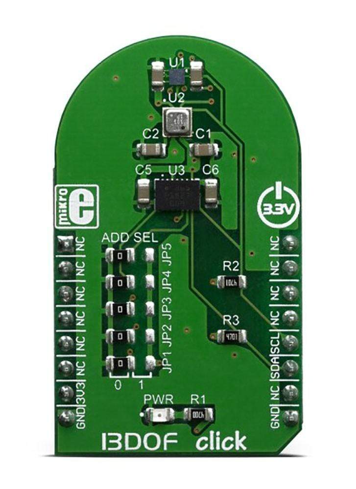
The 13DOF Click Board™ is based on the BME680 and the BMM150 sensor ICs. Also, the click contains BMI088 - a small, versatile 6DoF sensor module from Bosch. Altogether, this Click board™ integrates a triaxial accelerometer, triaxial gyroscope, triaxial geomagnetic, gas, humidity, pressure and temperature sensors on the single board. This allows very high integration and very small dimensions, at an affordable cost. The output of each MEMS is processed, digitized and available through the I2C communication interface. The data can be oversampled by the sensor ICs by themselves, in order to achieve as reliable data readings as possible. As already mentioned, the features of this click are numerous.
The BMM150 geomagnetic sensor from Bosch is a standalone sensor for consumer market applications. It allows measurements of the magnetic field in three perpendicular axes. The sensor is carefully tuned and a perfect match for the demanding requirements of all 3-axis mobile apps such as electronic compass, navigation or augmented reality. An application-specific circuit (ASIC) converts the output of the geomagnetic sensor to digital results which can be read out over the industry-standard digital I2C interface. The package and interfaces of the BMM150 have been designed to match a multitude of hardware requirements. As the sensor features an ultra-small footprint and a flat package, it is ingeniously suited for mobile applications, such as cell phones, handhelds, computer peripherals, man-machine interfaces, virtual reality features, game controllers, and others.
The BMI088 is an inertial measurement unit (IMU) for the detection of movements and rotations in 6 degrees of freedom (6DoF). It reflects the full functionality of a triaxial, low-g acceleration sensor and at the same time, it is capable to measure angular rates. Both – acceleration and angular rate – in three perpendicular room dimensions, the x-, y- and z-axis. The BMI088 is designed to meet all requirements for consumer applications such as gaming and pointing devices, HMI and image stabilization (DSC and camera-phone). It also senses tilt, motion, inactivity and shock vibration in cell phones, handhelds, computer peripherals, HMI interfaces, virtual reality features and game controllers. An ASIC converts the output of the MEMS, developed, produced and tested in BOSCH facilities. To provide maximum performance and reliability each device is tested and ready-to-use calibrated.
On the other side, the BME680 - a small, high performance, low power, the 4-in-1 sensor is in charge of the gas, humidity, pressure and temperature measurements. It also features very low power consumption, for example, 3.7 µA is typical at 1 Hz humidity, pressure and temperature measurement mode. It also features a very high accuracy humidity sensor (tolerance ±3% r.H. and hysteresis ±1.5% r.H.), a pressure sensor with only 0.12 Pa RMS Noise (equivalent to 1.7 cm of altitude) and a very low temperature offset drift, and a gas sensor with direct indoor air quality (IAQ) index output system. In principle, the IAQ index output is in an index that can have values between 0 and 500 with a resolution of 1 to indicate or quantify the quality of the air available in the surrounding. It greatly simplifies the categorization of the air quality measurements.
The 13DOF Click Board™ supports the I2C communication interface, allowing it to be used with a wide range of different MCUs. The I2C slave address for the communication can be selected by moving SMD jumpers grouped under the COMM SEL to an appropriate position.
The 13DOF Click Board™ is designed to be operated only with a 3.3V logic level. A proper logic voltage level conversion should be performed before the Click board™ is used with MCUs with logic levels of 5V.
SPECIFICATIONS
Type | Acceleration,Environmental,Gyroscope,Motion |
Applications | It is a perfect solution for the development of different types of motion detection and MotionTracking™ applications: motion-based game controllers, 3D and gesture controllers, IoT applications, wearable motion-sensing applications, and similar applications. |
On-board modules | BMM150 - geomagnetic sensor from Bosch, BME680 – Low power gas, pressure, temperature and humidity sensor from Bosch, BMI088 – small, versatile 6Dof sensor module from Bosch |
Key Features | small dimensions and its low power consumption enable the integration in battery-powered or frequency-coupled devices |
Interface | I2C |
Compatibility | mikroBUS |
Click board size | M (42.9 x 25.4 mm) |
Input Voltage | 3.3V |
PINOUT DIAGRAM
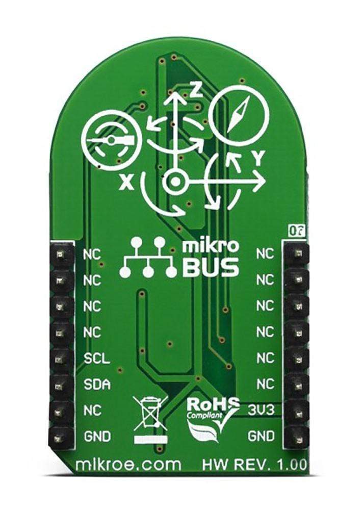
This table shows how the pinout on the 13DOF Click Board™ corresponds to the pinout on the mikroBUS™ socket (the latter shown in the two middle columns).
Notes | Pin | Pin | Notes | ||||
---|---|---|---|---|---|---|---|
NC | 1 | AN | PWM | 16 | NC | ||
NC | 2 | RST | INT | 15 | NC | ||
NC | 3 | CS | RX | 14 | NC | ||
NC | 4 | SCK | TX | 13 | NC | ||
NC | 5 | MISO | SCL | 12 | SCL | I2C Clock | |
NC | 6 | MOSI | SDA | 11 | SDA | I2C Data | |
Power Supply | 3.3V | 7 | 3.3V | 5V | 10 | NC | |
Ground | GND | 8 | GND | GND | 9 | GND | Ground |
ONBOARD SETTINGS AND INDICATORS
Label | Name | Default | Description |
---|---|---|---|
LD1 | PWR | - | Power LED Indicator |
JP1-JP5 | ADD SEL | Left | Slave I2C address LSB selection: left position 0, right position 1 |
Software Support
We provide a library for the 13DOF Click Board™ on our LibStock page, as well as a demo application (example), developed using MikroElektronika compilers. The demo can run on all the main MikroElektronika development boards.
Library Description
The library covers all the necessary functions to control the 13DOF Click Board™. The library performs a standard I2C interface communication.
Key Functions
float c13dof_bme680_getAmbientData( uint8_t dataIn )
- Get BME680 ambient data function.void c13dof_bmm150_readGeoMagData( int16_t *magX, int16_t *magY, int16_t *magZ, uint16_t *resHall )
- Get BMM150 Geomagnetic sensors data function.void c13dof_bmi088_readAccel( int16_t *accelX, int16_t *accelY, int16_t *accelZ )
- Read Accel X-axis, Y-axis and Z-axis function.
Example Description
The application is composed of three sections :
- System Initialization - Initializes I2C and start to write log.
- Application Initialization - Initialization driver enables - I2C, initializes BME680 Low power gas, pressure, temperature & humidity sensor, BMI088 6-axis Motion Tracking Sensor and BMM150 Geomagnetic Sensor, also write log.
- Application Task - (code snippet) This is an example that demonstrates the use of the 13DOF Click Board™. Measured and display temperature in degrees Celsius [ °C ], humidity data [ % ], pressure [ mbar ] and gas resistance data from the BME680 sensor. Measured and display Accel and Gyro data coordinates values for X-axis, Y-axis and Z-axis from the BMI088 sensor. Measured and display Geomagnetic data coordinates values for X-axis, Y-axis and Z-axis from the BMM150 sensor. Results are being sent to the Usart Terminal where you can track their changes. All data logs write on USB UART change every 2 sec.
void applicationTask() { temperature = c13dof_bme680_getTemperature(); Delay_10ms(); mikrobus_logWrite( " | BME680 |", _LOG_LINE ); mikrobus_logWrite( "----------------------------------------------------------", _LOG_LINE ); mikrobus_logWrite( " ", _LOG_TEXT ); mikrobus_logWrite( " Temperature : ", _LOG_TEXT ); FloatToStr( temperature, logText ); mikrobus_logWrite( logText, _LOG_TEXT ); mikrobus_logWrite( degCel, _LOG_LINE ); humidity = c13dof_bme680_getHumidity(); Delay_10ms(); mikrobus_logWrite( " ", _LOG_TEXT ); mikrobus_logWrite( " Humidity : ", _LOG_TEXT ); FloatToStr( humidity, logText ); mikrobus_logWrite( logText, _LOG_TEXT ); mikrobus_logWrite( " %", _LOG_LINE ); pressure = c13dof_bme680_getPressure(); Delay_10ms(); mikrobus_logWrite( " ", _LOG_TEXT ); mikrobus_logWrite( " Pressure : ", _LOG_TEXT ); FloatToStr( pressure, logText ); mikrobus_logWrite( logText, _LOG_TEXT ); mikrobus_logWrite( " mbar", _LOG_LINE ); gasRes = c13dof_bme680_getGasResistance(); Delay_10ms(); mikrobus_logWrite( " ", _LOG_TEXT ); mikrobus_logWrite( " Gas Resistance : ", _LOG_TEXT ); LongWordToStr( gasRes, logText ); ltrim( logText ); mikrobus_logWrite( logText, _LOG_LINE ); mikrobus_logWrite( "----------------------------------------------------------", _LOG_LINE ); readyCheck = c13dof_bmm150_checkReady(); while ( readyCheck != _C13DOF_BMM150_DATA_READY ) { readyCheck = c13dof_bmm150_checkReady(); } c13dof_bmi088_readAccel( &accelX, &accelY, &accelZ ); Delay_10ms(); c13dof_bmi088_readGyro( &gyroX, &gyroY, &gyroZ ); Delay_10ms(); c13dof_bmm150_readGeoMagData( &magX, &magY, &magZ, &RHall ); Delay_10ms(); mikrobus_logWrite( " BMI088 | BMM150", _LOG_LINE ); mikrobus_logWrite( "----------------------------------------------------------", _LOG_LINE ); mikrobus_logWrite( "| Accel | Gyro | Mag |",_LOG_LINE ); mikrobus_logWrite( "----------------------------------------------------------", _LOG_LINE ); mikrobus_logWrite( " Accel X :", _LOG_TEXT ); IntToStr( accelX, logText ); mikrobus_logWrite( logText, _LOG_TEXT ); mikrobus_logWrite( " | ", _LOG_TEXT ); mikrobus_logWrite( " Gyro X :", _LOG_TEXT ); IntToStr( gyroX, logText ); mikrobus_logWrite( logText, _LOG_TEXT ); mikrobus_logWrite( " | ", _LOG_TEXT ); mikrobus_logWrite( " Mag X :", _LOG_TEXT ); IntToStr( magX, logText ); mikrobus_logWrite( logText, _LOG_TEXT ); mikrobus_logWrite( " | ", _LOG_LINE ); mikrobus_logWrite( " Accel Y :", _LOG_TEXT ); IntToStr( accelY, logText ); mikrobus_logWrite( logText, _LOG_TEXT ); mikrobus_logWrite( " | ", _LOG_TEXT ); mikrobus_logWrite( " Gyro Y :", _LOG_TEXT ); IntToStr( gyroY, logText ); mikrobus_logWrite( logText, _LOG_TEXT ); mikrobus_logWrite( " | ", _LOG_TEXT ); mikrobus_logWrite( " Mag Y :", _LOG_TEXT ); IntToStr( magY, logText ); mikrobus_logWrite( logText, _LOG_TEXT ); mikrobus_logWrite( " | ", _LOG_LINE ); mikrobus_logWrite( " Accel Z :", _LOG_TEXT ); IntToStr( accelZ, logText ); mikrobus_logWrite( logText, _LOG_TEXT ); mikrobus_logWrite( " | ", _LOG_TEXT ); mikrobus_logWrite( " Gyro Z :", _LOG_TEXT ); IntToStr( gyroZ, logText ); mikrobus_logWrite( logText, _LOG_TEXT ); mikrobus_logWrite( " | ", _LOG_TEXT ); mikrobus_logWrite( " Mag Z :", _LOG_TEXT ); IntToStr( magZ, logText ); mikrobus_logWrite( logText, _LOG_TEXT ); mikrobus_logWrite( " | ", _LOG_LINE ); mikrobus_logWrite( "----------------------------------------------------------", _LOG_LINE ); mikrobus_logWrite( "----------------------------------------------------------", _LOG_LINE ); Delay_1sec(); Delay_1sec(); }
The full application code, and ready to use projects can be found on our LibStock page.
Other mikroE Libraries used in the example:
- I2C
- UART
- Conversions
Additional Notes and Information
Depending on the development board you are using, you may need a USB UART click, USB UART 2 click or RS232 click to connect to your PC, for development systems with no UART to USB interface available on the board. The terminal available in all MikroElektronika compilers, or any other terminal application of your choice, can be used to read the message.
MIKROSDK
The 13DOF Click Board™ is supported with mikroSDK - MikroElektronika Software Development Kit. To ensure proper operation of mikroSDK compliant Click board™ demo applications, mikroSDK should be downloaded from the LibStock and installed for the compiler you are using.
Frequently Asked Questions
Have a Question?
Be the first to ask a question about this.