


Mikroelektronika d.o.o.
Terminal Click-Platine
Terminal Click-Platine
SKU: MIKROE-3745
Verfügbarkeit für Abholungen konnte nicht geladen werden

Key Features
Overview
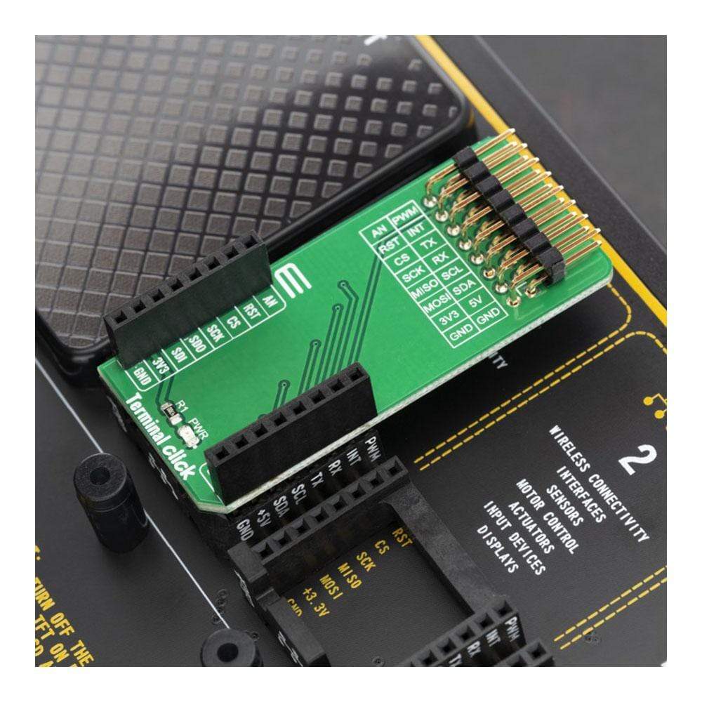
The Ultimate Solution for MikroBus Signal Access: The Terminal Click Board™
Unlock the true potential of your MikroBus signals with the innovative Terminal Click Board™! Whether you're looking to harness the power of I2C or SPI interfaces, this cutting-edge solution is tailor-made for the task.
Why Choose the Terminal Click Board™?
Revolutionize the way you interact with MikroBus signals using our state-of-the-art Terminal Click Board™. With its seamless compatibility, you can seamlessly integrate a Bus Analyzer like the renowned Total Phase Beagle I2C/SPI Sniffer. This means you'll have unparalleled insight into your bus operations, leading to enhanced efficiency and error detection.
Unleash the Power of Connectivity
The Terminal Click Board™ doesn't stop at signal analysis — it's also your gateway to driving Click Board™ Boards from a PC Host Adapter. Imagine the possibilities with the exceptional Total Phase Aardvark or the lightning-fast Cheetah adapter. This combination unlocks new horizons for your projects, offering you the control and versatility you've always craved.
Features at a Glance
- Seamless integration with MikroBus signals
- Full compatibility with I2C and SPI interfaces
- Connectivity with Total Phase Beagle I2C/SPI Sniffer for in-depth analysis
- Empower Click Board™ Boards with PC Host Adapters like Total Phase Aardvark or Cheetah
Upgrade Your Signal Access Today!
Don't miss out on the opportunity to supercharge your MikroBus signal utilization. The Terminal Click Board™ is your ticket to streamlined analysis and unmatched connectivity. Get ready to take your projects to new heights — order your Terminal Click Board™ now!
Downloads
Die ultimative Lösung für den MikroBus-Signalzugriff: Das Terminal Click Board™
Schöpfen Sie das wahre Potenzial Ihrer MikroBus-Signale mit dem innovativen Terminal Click Board™! Egal, ob Sie die Leistung von I2C- oder SPI-Schnittstellen nutzen möchten, diese innovative Lösung ist maßgeschneidert für diese Aufgabe.
Warum sollten Sie sich für das Terminal Click Board™ entscheiden?
Revolutionieren Sie die Art und Weise, wie Sie mit MikroBus-Signalen interagieren, indem Sie unser hochmodernes Terminal Click Board™ verwenden. Dank seiner nahtlosen Kompatibilität können Sie einen Busanalysator wie den renommierten Total Phase Beagle I2C/SPI Sniffer nahtlos integrieren. Dies bedeutet, dass Sie beispiellose Einblicke in Ihre Busvorgänge erhalten, was zu verbesserter Effizienz und Fehlererkennung führt.
Entfesseln Sie die Kraft der Konnektivität
Das Terminal Click Board™ beschränkt sich nicht nur auf die Signalanalyse – es ist auch Ihr Tor zur Ansteuerung von Click Board™-Boards von einem PC-Hostadapter aus. Stellen Sie sich die Möglichkeiten mit dem außergewöhnlichen Total Phase Aardvark oder dem blitzschnellen Cheetah-Adapter vor. Diese Kombination eröffnet neue Horizonte für Ihre Projekte und bietet Ihnen die Kontrolle und Vielseitigkeit, nach der Sie sich immer gesehnt haben.
Funktionen auf einen Blick
- Nahtlose Integration mit MikroBus-Signalen
- Volle Kompatibilität mit I2C- und SPI-Schnittstellen
- Konnektivität mit Total Phase Beagle I2C/SPI Sniffer für eingehende Analysen
- Empower Click Board™-Boards mit PC-Hostadaptern wie Total Phase Aardvark oder Cheetah
Aktualisieren Sie noch heute Ihren Signalzugriff!
Verpassen Sie nicht die Gelegenheit, die Signalnutzung Ihres MikroBus zu verbessern. Das Terminal Click Board™ ist Ihr Ticket für optimierte Analysen und unübertroffene Konnektivität. Machen Sie sich bereit, Ihre Projekte auf ein neues Niveau zu heben – bestellen Sie jetzt Ihr Terminal Click Board™!
| General Information | |
|---|---|
Part Number (SKU) |
MIKROE-3745
|
Manufacturer |
|
| Physical and Mechanical | |
Weight |
0.021 kg
|
| Other | |
EAN |
8606018716937
|
Frequently Asked Questions
Have a Question?
Be the first to ask a question about this.