

Mikroelektronika d.o.o.
Gyro 5 Click-Board
Gyro 5 Click-Board
SKU: MIKROE-3669
Verfügbarkeit für Abholungen konnte nicht geladen werden


Overview
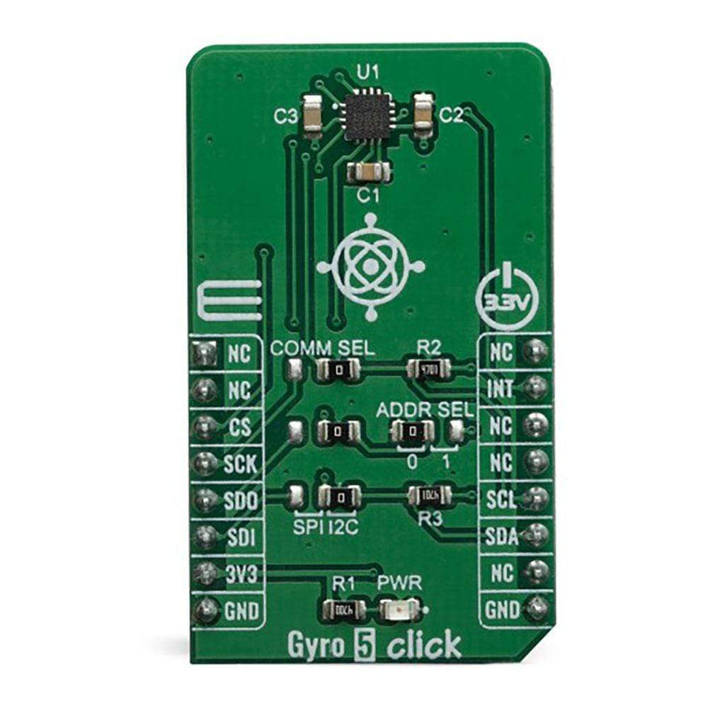
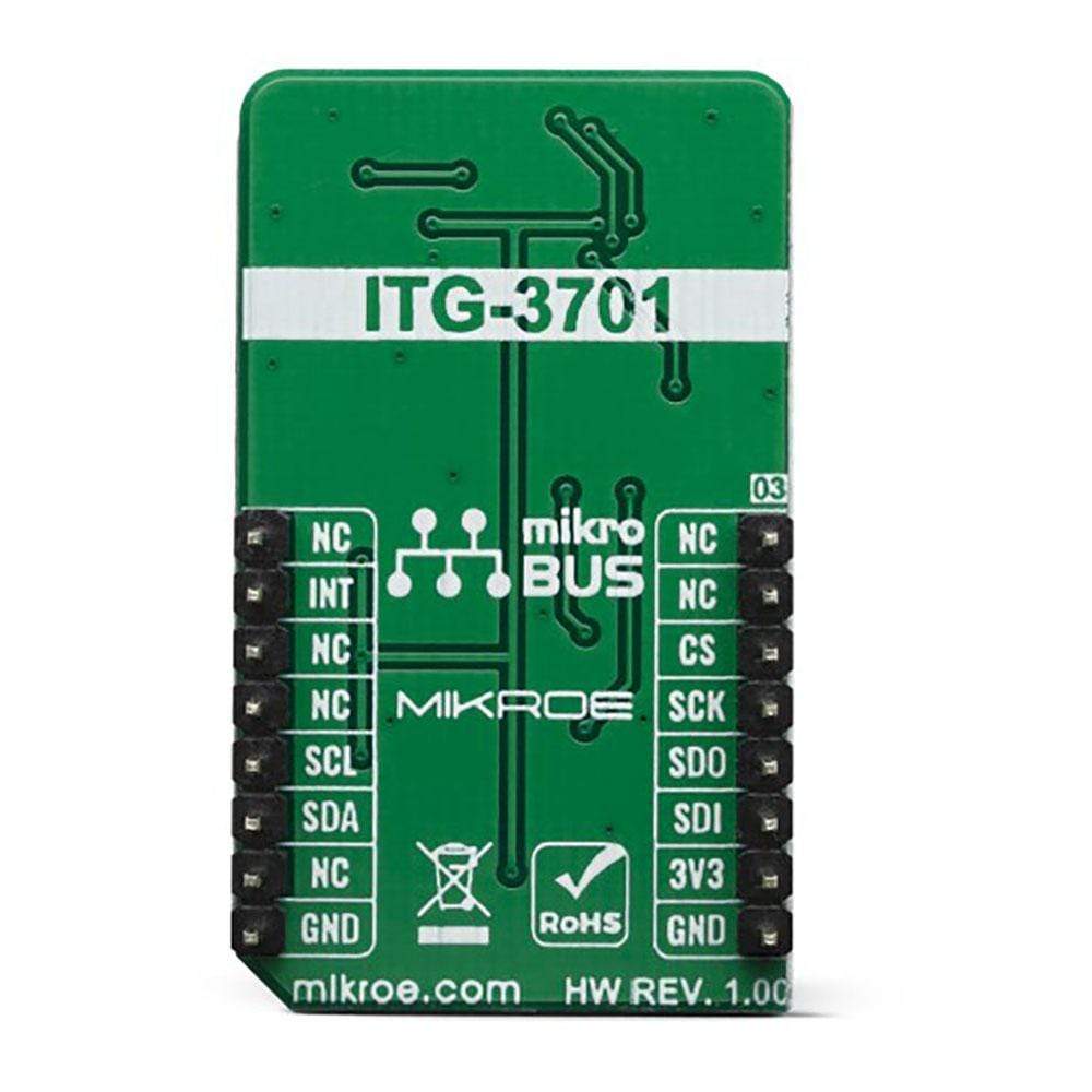
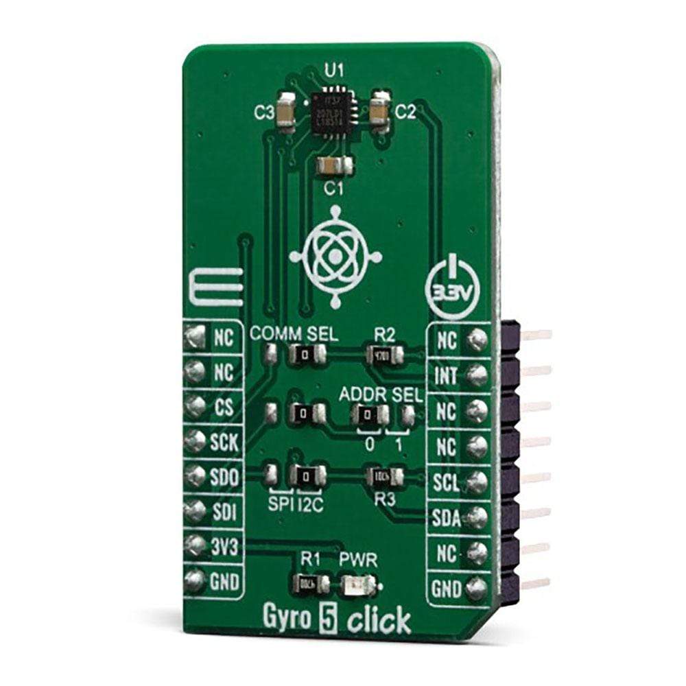
The Gyro 5 Click Board™ is a three-axis gyroscope Click Board™ that can sense motion over three perpendicular axes. It is equipped with the ITG-3701, a three-axis digital gyroscope. This IC incorporates microelectromechanical sensing elements (MEMS), produced using a proprietary CMOS micromachining technology. This technology allows for excellent stability and linearity over temperature. The angular data is available in a 16-bit format, along with the device’s die temperature data. Gyro 5 Click can be used for angular speed up to 4000 degrees per second (DPS), it features a FIFO buffer, two dedicated interrupt lines, and on-chip data processing for optimized firmware development.
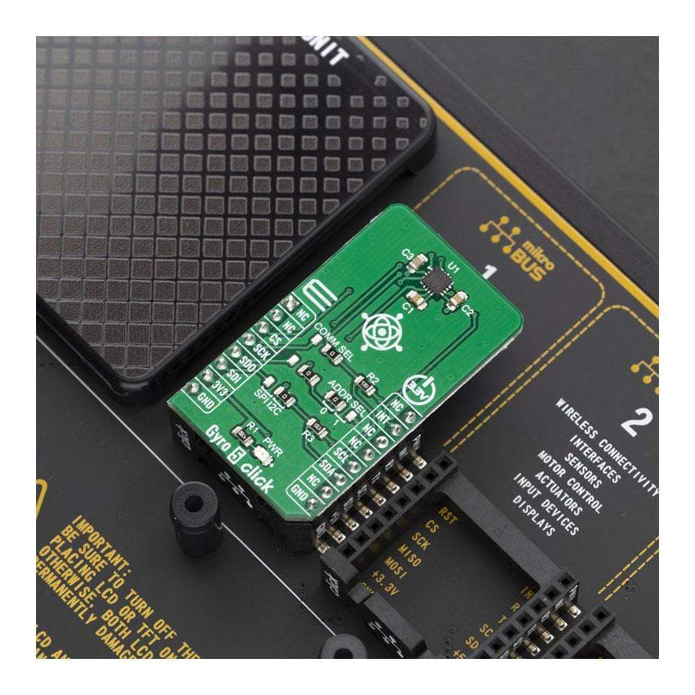
The Gyro 5 Click Board™ is supported by a mikroSDK compliant library, which includes functions that simplify software development. This Click Board™ comes as a fully tested product, ready to be used on a system equipped with the mikroBUS™ socket.
Downloads
Das Gyro 5 Click Board™ ist ein dreiachsiges Gyroskop Click Board™, das Bewegungen über drei senkrechte Achsen erfassen kann. Es ist mit dem ITG-3701 ausgestattet, einem dreiachsigen digitalen Gyroskop. Dieser IC enthält mikroelektromechanische Sensorelemente (MEMS), die mit einer proprietären CMOS-Mikrobearbeitungstechnologie hergestellt werden. Diese Technologie ermöglicht ausgezeichnete Stabilität und Linearität über die Temperatur. Die Winkeldaten sind in einem 16-Bit-Format verfügbar, zusammen mit den Chiptemperaturdaten des Geräts. Gyro 5 Click kann für Winkelgeschwindigkeiten von bis zu 4000 Grad pro Sekunde (DPS) verwendet werden und verfügt über einen FIFO-Puffer, zwei dedizierte Interruptleitungen und On-Chip-Datenverarbeitung für eine optimierte Firmware-Entwicklung.
Das Gyro 5 Click Board™ wird von einer mikroSDK-kompatiblen Bibliothek unterstützt, die Funktionen enthält, die die Softwareentwicklung vereinfachen. Dieses Click Board™ wird als vollständig getestetes Produkt geliefert und ist bereit für den Einsatz auf einem System, das mit der mikroBUS™-Buchse ausgestattet ist.
| General Information | |
|---|---|
Part Number (SKU) |
MIKROE-3669
|
Manufacturer |
|
| Physical and Mechanical | |
Weight |
0.018 kg
|
| Other | |
EAN |
8606018716494
|
Frequently Asked Questions
Have a Question?
Be the first to ask a question about this.