


Mikroelektronika d.o.o.
Gyro 4 Click-Board
Gyro 4 Click-Board
SKU: MIKROE-3661
Verfügbarkeit für Abholungen konnte nicht geladen werden


Overview
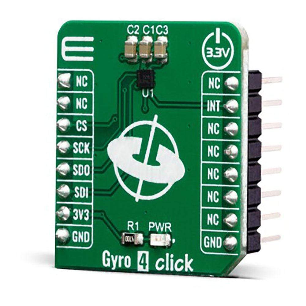
The Gyro 4 Click Board™ is a two-axis MEMS gyroscope for optical image stabilization applications. It is equipped with the L20G20IS, that includes a sensing element and an IC interface capable of providing the measured angular rate to the application through an SPI digital interface. The angular data is available in a 16-bit format, along with 12-bit device’s die temperature data. The IC interface is manufactured using a CMOS process that allows a high level of integration to design a dedicated circuit which is trimmed to better match the characteristics of the sensing element.
Downloads
Das Gyro 4 Click Board™ ist ein zweiachsiges MEMS-Gyroskop für Anwendungen zur optischen Bildstabilisierung. Es ist mit dem L20G20IS ausgestattet, das ein Sensorelement und eine IC-Schnittstelle enthält, die die gemessene Winkelgeschwindigkeit über eine digitale SPI-Schnittstelle an die Anwendung übermitteln kann. Die Winkeldaten sind in einem 16-Bit-Format verfügbar, zusammen mit den Chiptemperaturdaten des 12-Bit-Geräts. Die IC-Schnittstelle wird in einem CMOS-Prozess hergestellt, der ein hohes Maß an Integration ermöglicht, um einen dedizierten Schaltkreis zu entwickeln, der so getrimmt ist, dass er besser zu den Eigenschaften des Sensorelements passt.
| General Information | |
|---|---|
Part Number (SKU) |
MIKROE-3661
|
Manufacturer |
|
| Physical and Mechanical | |
Weight |
0.017 kg
|
| Other | |
EAN |
8606018716449
|
Frequently Asked Questions
Have a Question?
Be the first to ask a question about this.