Ambient 7 Click-Platine
Overview
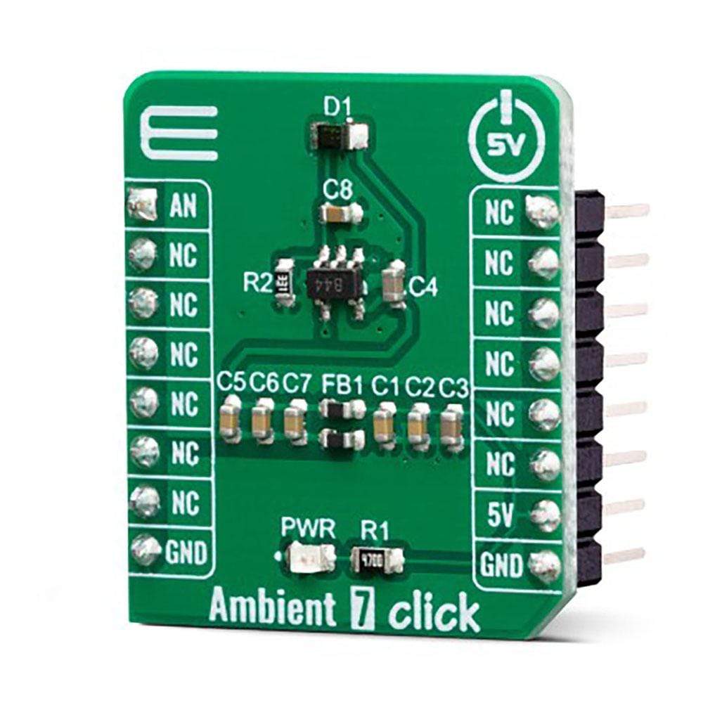
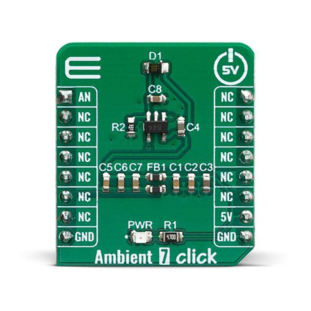
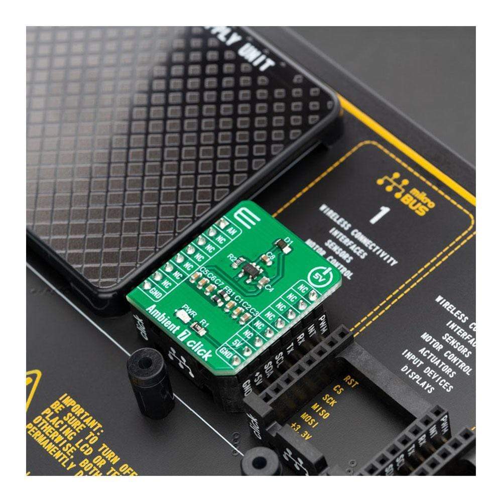
Das Ambient 7 Click Board™ ist ein Click Board™ zur Lichtintensitätserfassung und -messung, das über einen präzisen Lichtintensitätssensor mit der Bezeichnung SFH 5701 A01 von Osram Opto Semiconductors verfügt. Es bietet eine hohe Messgenauigkeit in einem weiten Bereich der tatsächlichen Lichtintensität. Die spektrale Reaktion des Sensors ist so kalibriert, dass sie der spektralen Reaktion des menschlichen Auges sehr nahe kommt. Dank seines hohen Integrationsgrads erfordert der Sensor nur eine minimale Anzahl externer Komponenten.
The influence of the light source type on the measurement accuracy is quite reduced. The sensor is capable of converting the light intensity from any type of light source, including daylight, fluorescent light, LED light, incandescent light, and so on. It also features Integrated dark current suppression and thermal compensation, which helps eliminating enviromental effects to measurement results. Its low-power consumption, compact size, and high sensitivity, make this sensor an ideal solution for both the IoT light-sensing applications, but also for portable or handheld devices which utilize an accurate light intensity sensing, such as the TFT/LCD screens, keypad backlight, Smart TVs, cell phones, digital cameras, and similar.
How Does The Ambient 7 Click Board™ Work?
As mentioned previously, the Ambient 7 Click Board™ uses the SFH 5701 A01, an accurate light-intensity sensor from Osram Opto Semiconductors. This sensor has many features that make it a perfect solution for small designs such as the Ambient 7 Click Board™. One of these features is certainly its high level of integration, that allows a minimal number of external components, leaving room for an additional operational amplifier, labelled as OPA344, made by Texas Instruments, proven in many designs.
As the SFH 5701 A01 limits the output current proportionaly to ambient light intensity, it creates an analog voltage on the R2 resistor (shunt). That voltage is directly proportional to the flowing current and thus the ambient light intensity. The previously mentioned operational amplifier serves as a unity gain amplifier (buffer), to ensure good analog measurement signal integrity. The output of the unity gain amplifier is routed to the mikroBUS AN pin. The voltage on the AN pin can be measured bz internal ADC integrated in the main MCU on the development board.
The accuracy of SFH 5701 A01 sensor is not influenced by the light source type. It is calibrated so its spectral response is closely matched to a spectral response of the human eye. It is also worth to mention that the sensor qualification test plan is referenced to the guidelines of AEC-Q102 – a failure mechanism based stress test qualification for discrete optoelectronic semiconductors in automotive applications.
Built in thermal compensation ensures that the measurement results are valid in wide temperature range and thanks to integrated dark current suppression, the output signal while the sensor is exposed to dark environment is as minimal as possible. The sensor is operational in very wide Illuminance range – from 0.01lx up to 10000lx. In other words, it has linear response over 6 decades of illumination range.
The Ambient 7 Click Board™ is designed to be operated only with 5V logic level. A proper logic voltage level conversion should be performed before the Click Board™ is used with MCUs with logic levels of 3.3V.
SPECIFICATIONS
Type | Optical |
Applications | This sensor is an ideal solution for both the IoT light-sensing applications, but also for portable or handheld devices which utilize an accurate light intensity sensing, such as the TFT/LCD screens, keypad backlight, Smart TVs, cell phones, digital cameras, and similar. |
On-board modules | SFH 5701 A01, an accurate light-intensity sensor from Osram Opto Semiconductors. |
Key Features | A spectral response similar to human eye, low-power consumption, Integrated dark current suppression, Built in thermal compensation, Linear response over 6 decades of illumination range |
Interface | Analog |
Compatibility | mikroBUS |
Click Board™ size | S (28.6 x 25.4 mm) |
Input Voltage | 5V |
PINOUT DIAGRAM
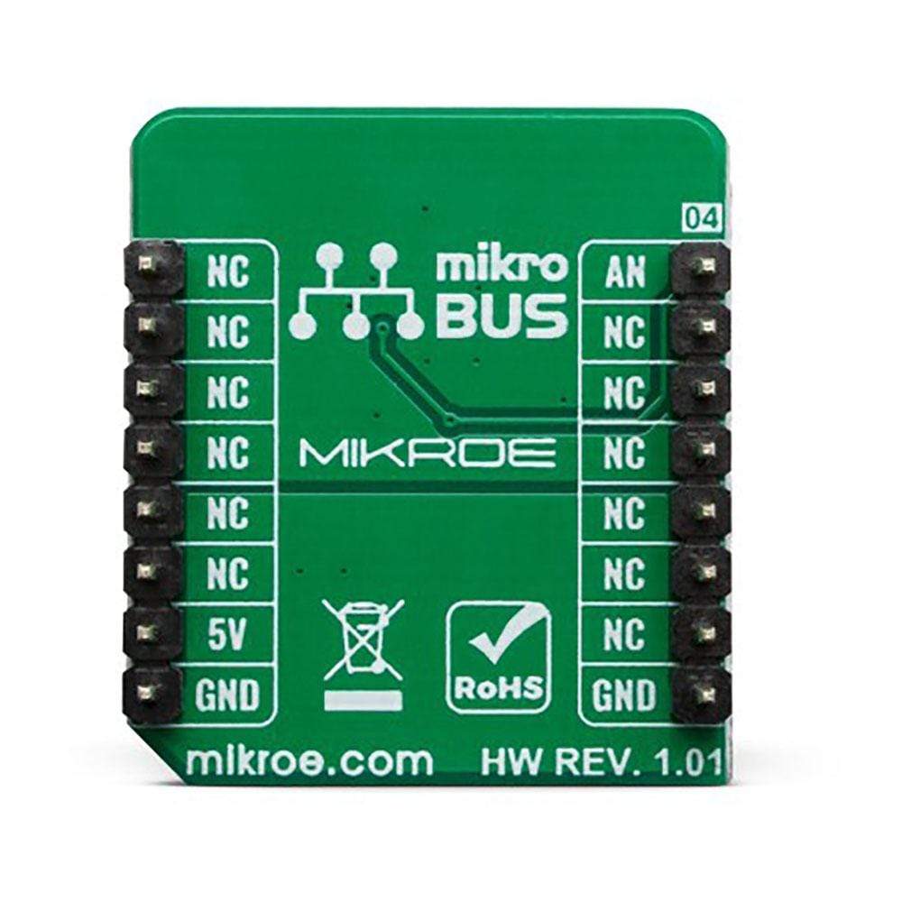
This table shows how the pinout on Ambient 7 Click Board™ corresponds to the pinout on the mikroBUS socket (the latter shown in the two middle columns).
Notes | Pin | Pin | Notes | ||||
---|---|---|---|---|---|---|---|
Analog Out | AN | 1 | AN | PWM | 16 | NC | |
NC | 2 | RST | INT | 15 | NC | ||
NC | 3 | CS | RX | 14 | NC | ||
NC | 4 | SCK | TX | 13 | NC | ||
NC | 5 | MISO | SCL | 12 | NC | ||
NC | 6 | MOSI | SDA | 11 | NC | ||
NC | 7 | 3.3V | 5V | 10 | 5V | Power supply | |
Ground | GND | 8 | GND | GND | 9 | GND | Ground |
ONBOARD JUMPERS AND SETTINGS
Label | Name | Default | Description |
---|---|---|---|
LD1 | PWR | - | Power LED Indicator |
Software Support
Software Support
We provide a library for the Ambient 7 Click Board™ on our LibStock page, as well as a demo application (example), developed using MikroElektronika compilers. The demo can run on all the main MikroElektronika development boards.
Library Description
The library contains ADC functions to completely setting and reading the value from the ADC channel that sends Ambient Click Board™. The ambient light measurement resolution depends on the ADC resolution you use.
Key Functions
void ambient7_adcInit()
- ADC init.void ambient7_adcSetInputChannel()
- ADC set input channel.uint32_t ambient7_adcRead()
- ADC read data.
Example Description
The application is composed of three sections :
- System Initialization - Initializes UART for logging data.
- Application Initialization - Initialization driver init and ADC init.
- Application Task - Reads ADC value and this data logs to USBUART every 1 sec..
- note - Illuminance range [EV] - from 0.01[lx] to 10k[lx] depending on the ADC you are using.
void applicationTask() { uint16_t ADC_value; char demoText[ 50 ]; ADC_value = ambient7_adcRead(); WordToStr(ADC_value, demoText); mikroBUS_logWrite(" ADC value: ", _LOG_TEXT); mikroBUS_logWrite(demoText, _LOG_LINE); Delay_ms( 500 ); }
The full application code, and ready to use projects can be found on our LibStock page.
Other mikroE Libraries used in the example:
- ADC Library.
- Conversions Library.
Additional Notes and Information
Depending on the development board you are using, you may need USB UART Click Board™, USB UART 2 Click Board™ or RS232 Click Board™ to connect to your PC, for development systems with no UART to USB interface available on the board. The terminal available in all MikroElektronika compilers, or any other terminal application of your choice, can be used to read the message.
MIKROSDK
The Ambient 7 Click Board™ is supported with mikroSDK - MikroElektronika Software Development Kit. To ensure proper operation of mikroSDK compliant Click Board™ demo applications, mikroSDK should be downloaded from the LibStock and installed for the compiler you are using.
Software Support
Software Support
We provide a library for the Ambient 7 Click Board™ on our LibStock page, as well as a demo application (example), developed using MikroElektronika compilers. The demo can run on all the main MikroElektronika development boards.
Library Description
The library contains ADC functions to completely setting and reading the value from the ADC channel that sends Ambient Click Board™. The ambient light measurement resolution depends on the ADC resolution you use.
Key Functions
void ambient7_adcInit()
- ADC init.void ambient7_adcSetInputChannel()
- ADC set input channel.uint32_t ambient7_adcRead()
- ADC read data.
Example Description
The application is composed of three sections :
- System Initialization - Initializes UART for logging data.
- Application Initialization - Initialization driver init and ADC init.
- Application Task - Reads ADC value and this data logs to USBUART every 1 sec..
- note - Illuminance range [EV] - from 0.01[lx] to 10k[lx] depending on the ADC you are using.
void applicationTask() { uint16_t ADC_value; char demoText[ 50 ]; ADC_value = ambient7_adcRead(); WordToStr(ADC_value, demoText); mikroBUS_logWrite(" ADC value: ", _LOG_TEXT); mikroBUS_logWrite(demoText, _LOG_LINE); Delay_ms( 500 ); }
The full application code, and ready to use projects can be found on our LibStock page.
Other mikroE Libraries used in the example:
- ADC Library.
- Conversions Library.
Additional Notes and Information
Depending on the development board you are using, you may need USB UART Click Board™, USB UART 2 Click Board™ or RS232 Click Board™ to connect to your PC, for development systems with no UART to USB interface available on the board. The terminal available in all MikroElektronika compilers, or any other terminal application of your choice, can be used to read the message.
MIKROSDK
The Ambient 7 Click Board™ is supported with mikroSDK - MikroElektronika Software Development Kit. To ensure proper operation of mikroSDK compliant Click Board™ demo applications, mikroSDK should be downloaded from the LibStock and installed for the compiler you are using.
Frequently Asked Questions
Have a Question?
Be the first to ask a question about this.