

Mikroelektronika d.o.o.
Temp-Log 6 Click-Platine
Temp-Log 6 Click-Platine
SKU: MIKROE-3437
Verfügbarkeit für Abholungen konnte nicht geladen werden


Overview
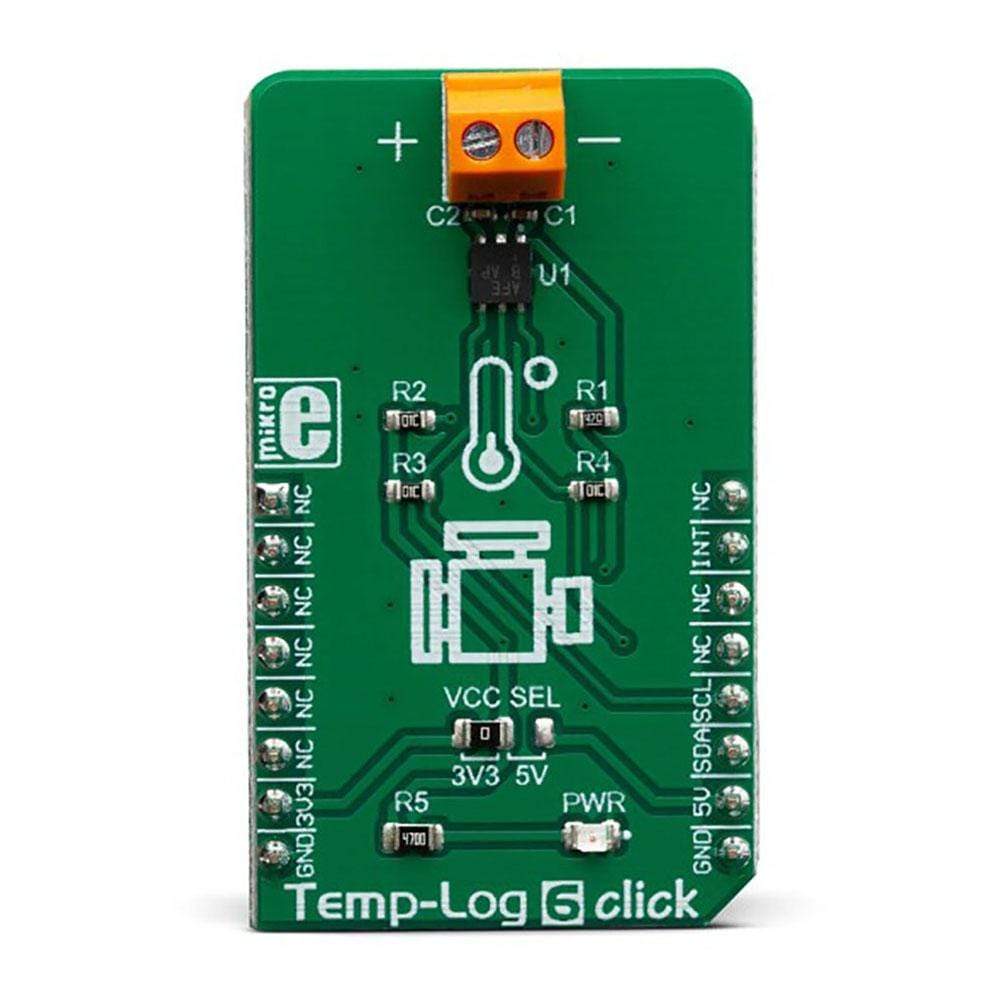
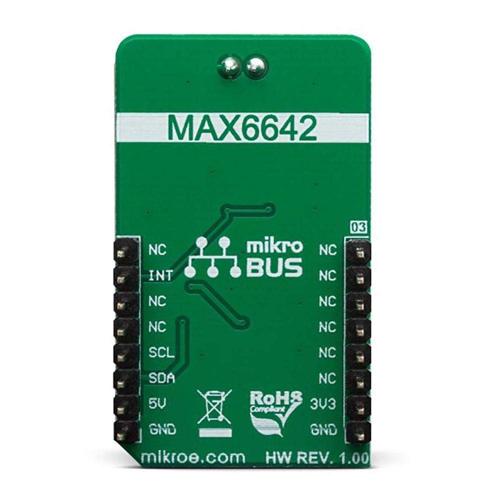
The Temp-Log 6 Click Board™ is a temperature sensing Click Board™, which features the MAX6642, a specifically designed IC, capable of measuring its own die temperature, as well as a temperature at a remote PN junction. This option makes Temp-Log 6 Click Board™ well-suited for monitoring the temperature of a CPU, GPU or FPGA, where the PN junction is typically a substrate PNP transistor on the die of the measured IC. Instead of measuring the PN junction of a specifically designed IC, the Temp-Log 6 Click Board™ can also use an external diode or a small-signal transistor. The MAX6642 can also report an ALERT signal if programmed temperature thresholds are exceeded.
Downloads
Das Temp-Log 6 Click Board™ ist ein Click Board™ mit Temperatursensor, das über den MAX6642 verfügt, einen speziell entwickelten IC, der seine eigene Chiptemperatur sowie die Temperatur an einer entfernten PN-Verbindung messen kann. Diese Option macht das Temp-Log 6 Click Board™ gut geeignet für die Überwachung der Temperatur einer CPU, GPU oder FPGA, bei der die PN-Verbindung typischerweise ein Substrat-PNP-Transistor auf dem Chip des gemessenen IC ist. Anstatt die PN-Verbindung eines speziell entwickelten IC zu messen, kann das Temp-Log 6 Click Board™ auch eine externe Diode oder einen Kleinsignaltransistor verwenden. Der MAX6642 kann auch ein ALERT-Signal melden, wenn programmierte Temperaturschwellen überschritten werden.
| General Information | |
|---|---|
Part Number (SKU) |
MIKROE-3437
|
Manufacturer |
|
| Physical and Mechanical | |
Weight |
0.019 kg
|
| Other | |
EAN |
8606018714841
|
Frequently Asked Questions
Have a Question?
Be the first to ask a question about this.