Temp&Hum 9 Click-Platine
Overview
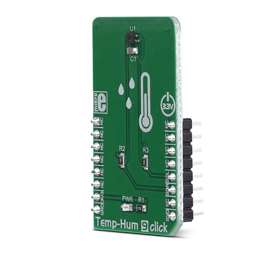
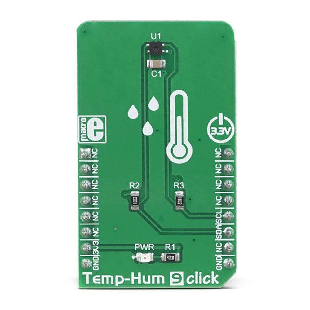
Das Temp-Hum 9 Click Board™ ist ein intelligentes Click Board™ zur Temperatur- und Feuchtigkeitsmessung, vollgepackt mit Funktionen, die eine einfache Integration in jedes Design ermöglichen. Es kann eine große Bandbreite an Temperatur- und relativen Feuchtigkeitswerten mit hoher Genauigkeit messen. Die auf diesem Click Board™ verwendeten SHTC3-Sensoren bieten das komplette Messsystem: kapazitiver RH-Sensor, Bandgap-Wärmesensor, analoge und digitale Datenverarbeitung und die I2C-Kommunikationsschnittstelle. Mit seiner guten Zuverlässigkeit über die Zeit, hohen Genauigkeit und geringen Hysterese ist es eine ideale Lösung für den Einsatz in verschiedenen Temperatur- und Feuchtigkeitsanwendungen.
The Temp-Hum 9 Click Board™ can measure the humidity in the range from 0 to 100 %RH and temperature in the range from -40 ℃ to +125 ℃ with a typical accuracy of ±2 %RH and ±0.2 ℃. It consumes very low amount of power while operated, and it can output the conversion values directly in physical units, thanks to the CMOSens® manufacturing technology. Featuring high reliability and long-term stability, high Signal-to-Noise (SNR) ratio, good accuracy, and low power consumption, the Temp-Hum 9 Click Board™ is an ideal solution for development of a range of different applications, including battery operated weather stations, thermostats and humidistats, microenvironment centers, respiratory therapy applications, air conditioners, and other similar applications.
How Does The Temp-Hum 9 Click Board™ Work?
The main component of the Temp-Hum 9 Click Board™ is the SHTC3, a relative humidity and temperature sensor with I²C Interface, by Sensirion. This sensor IC integrates two very accurate sensing components: temperature sensor, and relative humidity sensor. By utilizing the proprietary CMOSens® manufacturing technology, this sensor integrates the complete temperature and humidity measurement system on chip. The output data is processed and compensated by the SHTC3 IC itself, requiring only basic conversion formulas to be applied within the firmware of the host microcontroller (MCU). These conversion formulas are given in the SHTC3 datasheet, and provide readings in °C and %RH, directly.
The SHTC3 incorporates an accurate bandgap temperature sensor, which can measure the temperature in the range between -40°C and 125°C while retaining accuracy of ±0.8°C, typically. The accuracy is even greater if the range is narrowed down: when used over the range between 0°C and 60°C, the typical accuracy is ±0.2°C. Also, the repeatability of the temperature measurement is very good, in the range of 0.1°C. The SHTC3 sensor IC can be reliably used for prolonged periods of time, as it has a very low thermal drift of less than 0.02°C per year.
After the measurement has been converted by high-precision ADC, it is fed to a logic back-end which applies factory-calibrated correction and converts the raw data into a compensated value. By applying a simple conversion formula, the temperature measurement can be read directly in ℃. Note however, that the sensor will take some time to accommodate to the ambient temperature, especially if the temperature changes quickly, considering the thermal conductivity of the PCB itself. However, the Click board™ surface is not very large, resulting in lower thermal inertia.
The humidity sensor is a capacitor-based sensor which changes the capacitance proportionally to the relative humidity. However, the capacitance of this sensor is affected by changes of the ambient temperature, as well. The datasheet of the SHTC3 offers a map of the RH accuracy at different temperatures, covering a range of different values. The RH sensor accuracy varies in the range between ±2% and ±4%, depending on the measurement conditions. This table can be used to check the exact accuracy for some specific ℃ and %RH conditions.
After the measurement has been converted by high-precision ADC, it is fed to a logic back-end which applies factory-calibrated correction and converts the raw data into a compensated value. By applying a simple conversion formula, the temperature measurement can be read directly in %RH. Note that capacitor-based humidity sensors commonly suffer from a small hysteresis, which may occur if the sensor is used in very humid conditions for prolonged periods of time. However, this hysteresis is not irreversible. The SHTC3 datasheet specifies that its hysteresis should stay within the range of ±1 %RH.
The Temp-Hum 9 Click Board™ uses the I2C communication interface. It has pull-up resistors connected to the mikroBUS™ 3.3V rail. A proper conversion of logic voltage levels should be applied before the Click board™ is used with MCUs operated with 5V.
SPECIFICATIONS
Type | Temperature & humidity |
Applications | The Temp-Hum 9 Click Board™ is an ideal solution for development of a range of different applications, including battery operated weather stations, thermostats and humidistats, microenvironment centers, respiratory therapy applications, air conditioners, and other similar applications. |
On-board modules | SHTC3, a relative humidity and temperature sensor with I²C Interface, by Sensirion |
Key Features | The complete measurement stack on chip, thanks to the proprietary CMOSens® manufacturing process, advanced logic back-end offers calibrated data, low drift over time, high repeatability, etc. |
Interface | I2C |
Compatibility | mikroBUS |
Click board size | M (42.9 x 25.4 mm) |
Input Voltage | 3.3V |
PINOUT DIAGRAM
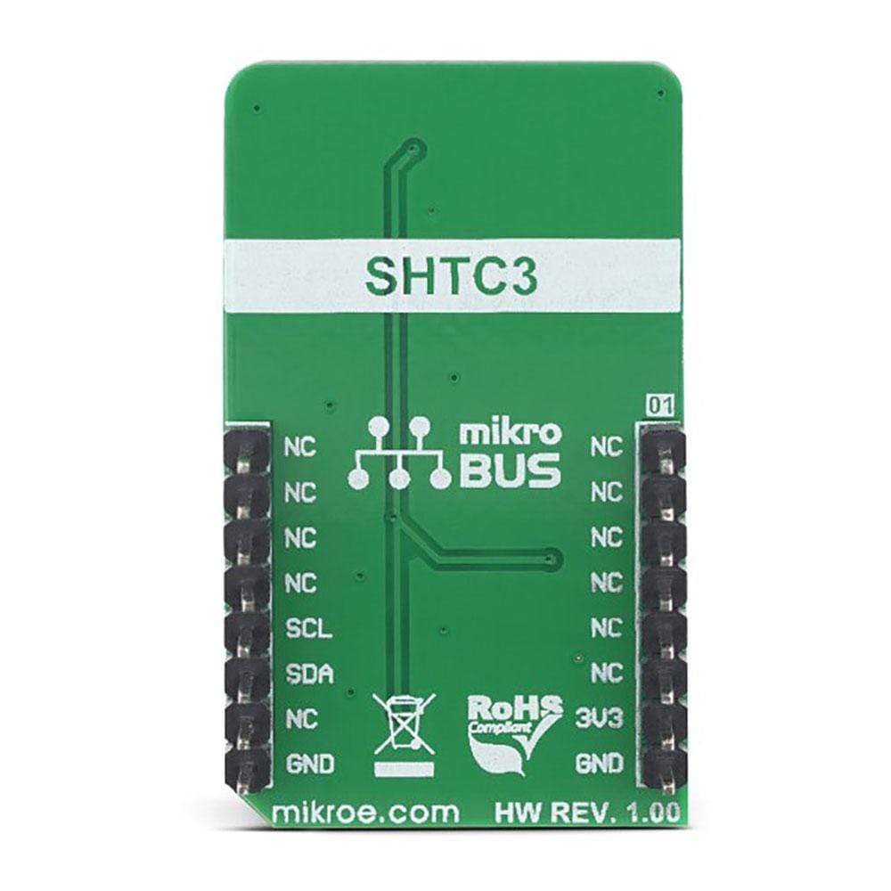
This table shows how the pinout of the Temp-Hum 9 Click Board™ corresponds to the pinout on the mikroBUS™ socket (the latter shown in the two middle columns).
Notes | Pin | Pin | Notes | ||||
---|---|---|---|---|---|---|---|
NC | 1 | AN | PWM | 16 | NC | ||
NC | 2 | RST | INT | 15 | NC | ||
NC | 3 | CS | RX | 14 | NC | ||
NC | 4 | SCK | TX | 13 | NC | ||
NC | 5 | MISO | SCL | 12 | SCL | I2C Clock | |
NC | 6 | MOSI | SDA | 11 | SDA | I2C Data | |
Power Supply | +3V3 | 7 | 3.3V | 5V | 10 | NC | |
Ground | GND | 8 | GND | GND | 9 | GND | Ground |
ONBOARD SETTINGS AND INDICATORS
Label | Name | Default | Description |
---|---|---|---|
PWR | PWR | - | Power LED indicator |
Software Support
We provide a library for the Temp-Hum 9 Click Board™ on our LibStock page, as well as a demo application (example), developed using MikroElektronika compilers. The demo can run on all the main MikroElektronika development boards.
Library Description
Library contains.
Key Functions
void temphum9_readRegister( uint16_t registerAddress_, uint8_t nData_, uint16_t *registerBuffer_ )
- reads one or two 16-bit registers.void temphum9_sendCommand( uint16_t command_ )
- issues (sends) command to device.void temhum9_getTemperatureAndHumidity( uint8_t mode_, float *measurementData)
- performs temperature and relative humidity measurement and calculates temperature and relative humidity.
Example Description
The application is composed of three sections :
- System Initialization - Initializes LOG and I2C.
- Application Initialization - Initializes I2C driver and sends SLEEP and WAKEUP dommands.
- Application Task - Performs simultaneous temperature and relative humidity measurements and logs both values.
void applicationTask( ) { mikrobus_logWrite( " ", _LOG_LINE ); temhum9_getTemperatureAndHumidity( _TEMPHUM9_NORMAL_MODE, &measurementData[0] ); FloatToStr( measurementData[0], text ); mikrobus_logWrite( "> > > Temperature : ", _LOG_TEXT ); mikrobus_logWrite( text, _LOG_TEXT ); mikrobus_logWrite( " C", _LOG_LINE ); FloatToStr( measurementData[1], text ); mikrobus_logWrite( "> > > Relative humidity : ", _LOG_TEXT ); mikrobus_logWrite( text, _LOG_TEXT ); mikrobus_logWrite( " %", _LOG_LINE ); mikrobus_logWrite( " ", _LOG_LINE ); Delay_ms(1000); }
The full application code, and ready to use projects can be found on our LibStock page.
Other mikroE Libraries used in the example:
I2C
UART
Conversions
Additional Notes and Information
Depending on the development board you are using, you may need USB UART click, USB UART 2 click or RS232 click to connect to your PC, for development systems with no UART to USB interface available on the board. The terminal available in all MikroElektronika compilers, or any other terminal application of your choice, can be used to read the message.
Frequently Asked Questions
Have a Question?
Be the first to ask a question about this.