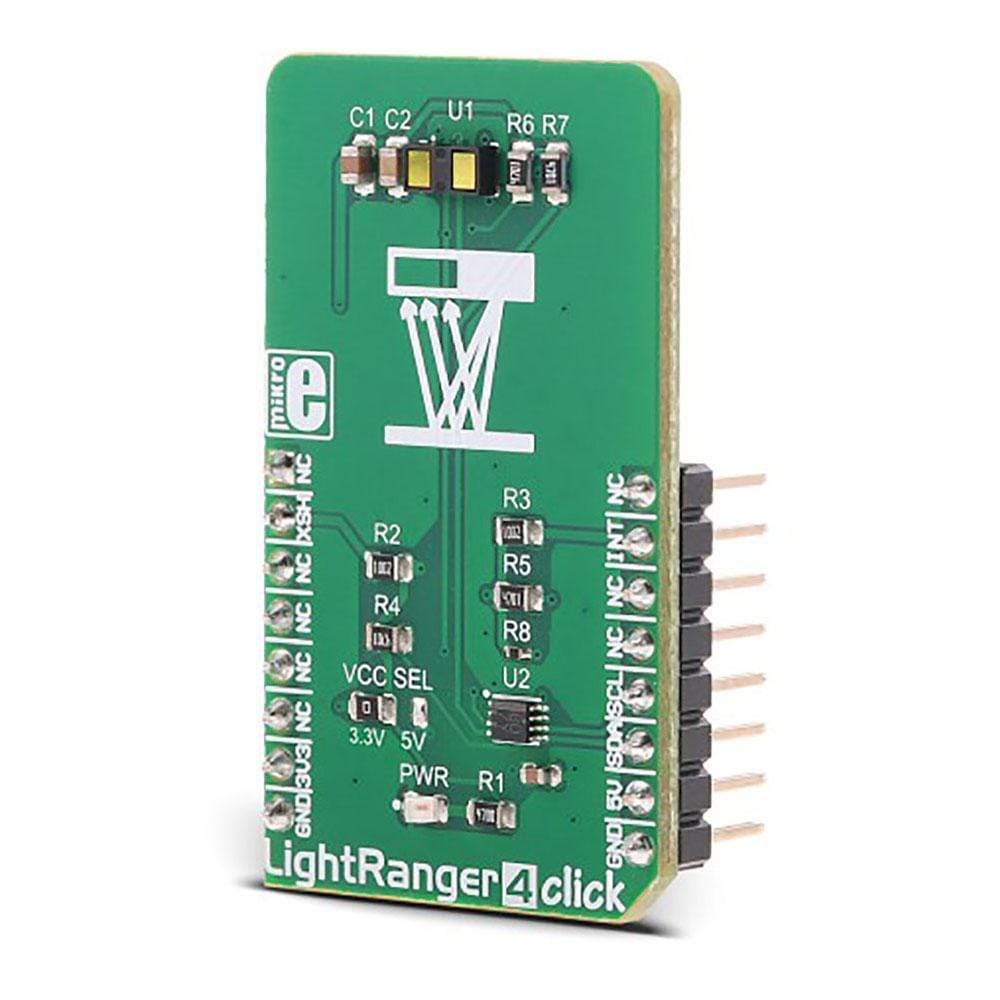
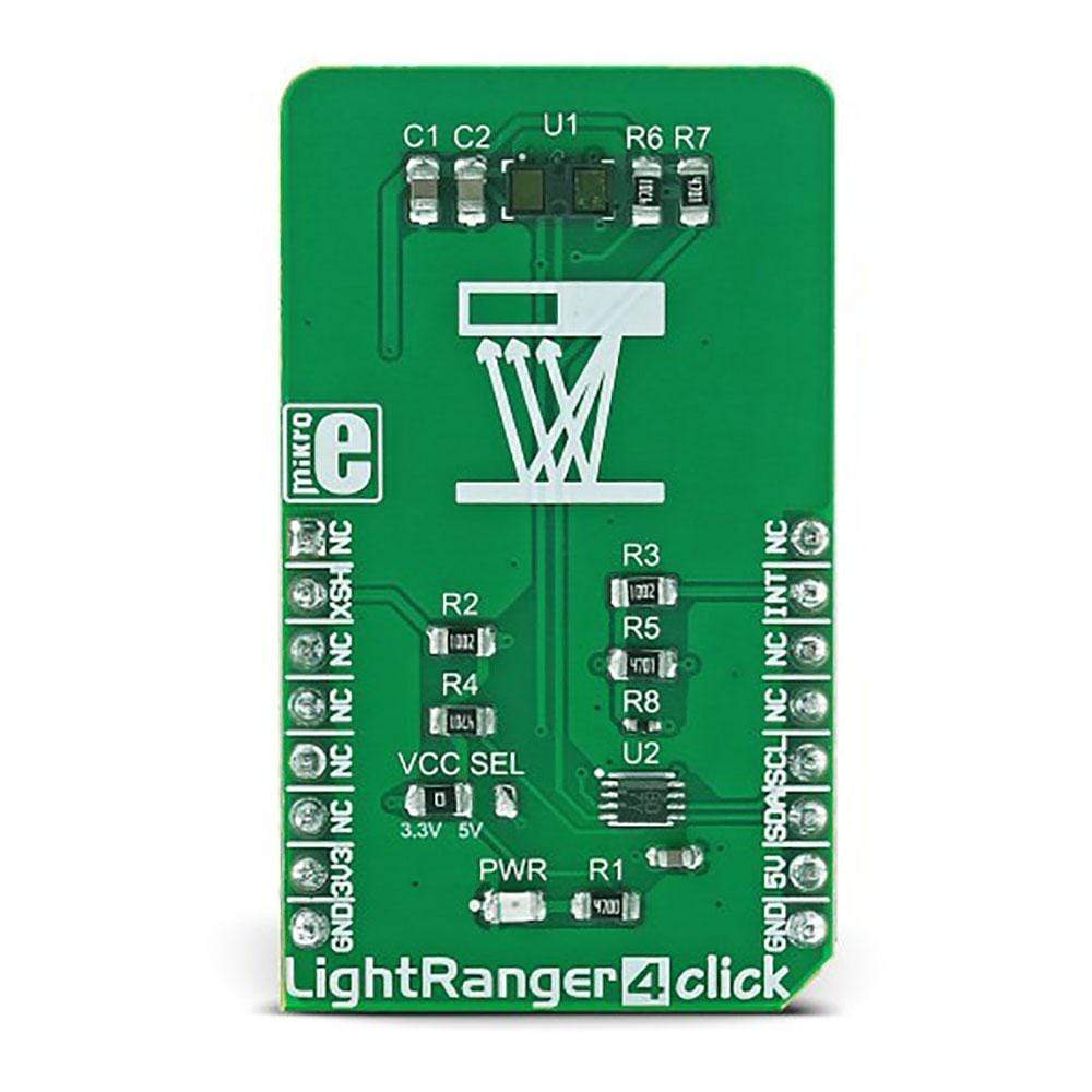
LightRanger 4 Click-Platine
Das Light Ranger 4 Click Board™ ist ein Click Board™ zur genauen Entfernungsmessung, das auf einem ToF-Messprinzip (Time of Flight) basiert. Das FlightSense-fähige VL53L1X-Entfernungsmessermodul von STMicroelectronics ist ein vollständiger Messstapel auf dem Chip. Es ist überraschend einfach zu handhaben, da dieses hochintegrierte Entfernungsmessermodul nur die I2C-Schnittstelle sowie die XSH- und INT-Pins zum Host-Controller freigibt. Es verfügt über den unsichtbaren Laseremitter der Klasse 1, der ein schmales Band eines harmlosen modulierten Lichtstrahls im IR-Bereich (940 nm) aussendet, sowie über physikalische Infrarotfilter und Optiken, um die beste Entfernungsmessungsleistung bei verschiedenen Umgebungslichtbedingungen mit einer Reihe von Abdeckungsfensteroptionen zu erreichen. Es kann Entfernungen bis zu 4000 mm mit einer Entfernungsmessungsfrequenz von bis zu 50 Hz messen.
ToF based light distance meters and rangefinders are one of the most accurate contactless distance measuring devices. The ability to precisely measure distance without making actual contact, allows Light Ranger 4 to be used in industry - for counting dimensions of goods in industry, controlling a safety area, building contactless digital measurement tools. Some other uses for this device could be building 3D visual guidance applications in robotics, for moving it through obstacles, and similar.
How Does The Light Ranger 4 Click Board™ Work?
The Light Ranger 4 Click Board™ uses the FlightSense™ enabled VL53L1X rangefinder module from STMicroelectronics. This sensor uses the Class1 laser emitter, which emits light in the range of 940 nm. The light emission is in the IR range of the spectrum and it is not visible by a human eye. It is received by the IR sensor and processed by the integrated sections of the VL53L1X, giving the result on the output register, available via the standard I2C interface. The device is rated as Class 1 LASER product, and it does not cause harmful eye injuries. However, it should not be pointed towards the eyes.
The highly integrated VL53L1X ToF sensor encompasses several integrated sections. It has an embedded MCU, OTP memory, RAM area, ROM area, ranging processing unit and the VCSEL driver. It exposes a simple I2C interface for the communication with the host MCU, offering a range of registers, used for configuring and status reporting. In addition, it offers an interrupt (INT) and XSH (XSHUT) pins routed to the mikroBUS™. Highly configurable interrupt engine allows this pin to be configured to generate interrupt signals for various events, alerting the host MCU about some important status changes, such as the Data Ready event, for example. It can be set to work in both open-drain configurations, as well as in the push-pull mode. Besides the INT pin, XSH pin is also avalible on the click board, which can be used for shuting down the main IC. The Click board™ is equipped with the 10K pull-up resistors, so it is advised to configure the INT and XSH pins in open-drain mode.
The measurement is done by comparing the modulation shift of the light in the reflected beam. Therefore, the range and the accuracy depend on the material of the measured object, as well as the photo - pollution of the IR spectrum. The module is designed to suppress the noise and interference, while the programmable Field of view from 15 to 27 degrees allows focused measurement and prevents beam scattering. The measurement is naturally affected by the IR reflectance of an object, so best results are achieved when measuring the distance of the objects that have high IR reflectance. The maximum range that can be measured is 4000mm, while the minimum operational range is 40mm. The measurement error is linear, and it grows with the distance. It stays within 10% of the distance.
Since the VL53L1X ToF sensor module is highly integrated and requires a minimum number of external components to work, this Click board™ has only one SMD jumper (VCC SEL) which can be used to set the power supply voltage between 3.3V and 5V, allowing both 3.3V and 5V tolerant MCUs to be interfaced with the Click board™. The RFD77402 module datasheet offers an extensive information about internal registers and how to configure them. However, the click comes with the library of functions that provide simplified operation and measurement. The use of these functions is demonstrated in the example, which can be used as the reference for custom design.
SPECIFICATIONS
Type | Optical |
Applications | Can be used for counting dimensions of goods in industry, controlling a safety area, building contactless digital measurement tools. Some other uses for this device could be building 3D visual guidance applications in robotics, for moving it through obstacles, and similar |
On-board modules | FlightSense™ enabled VL53L1X ToF sensor module, from STMicroelectronics |
Key Features | Contactless measurement between 40mm and up to 4000mm. The device is rated Class 1 laser product, operating in the IR (invisible) spectrum range. Integrated sections allow minimum number of external components to be used |
Interface | I2C |
Compatibility | mikroBUS |
Click board size | M (42.9 x 25.4 mm) |
Input Voltage | 3.3V or 5V |
PINOUT DIAGRAM
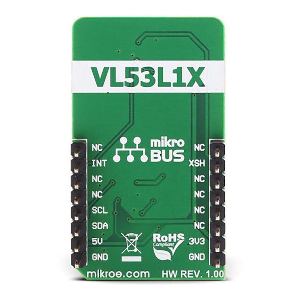
This table shows how the pinout on LightRanger 4 Click corresponds to the pinout on the mikroBUS™ socket (the latter shown in the two middle columns).
Notes | Pin | Pin | Notes | ||||
---|---|---|---|---|---|---|---|
NC | 1 | AN | PWM | 16 | NC | ||
Shut Down | XSH | 2 | RST | INT | 15 | INT | Interrupt OUT |
NC | 3 | CS | RX | 14 | NC | ||
NC | 4 | SCK | TX | 13 | NC | ||
NC | 5 | MISO | SCL | 12 | SCL | I2C Clock | |
NC | 6 | MOSI | SDA | 11 | SDA | I2C Data | |
Power supply | 3.3V | 7 | 3.3V | 5V | 10 | NA | |
Ground | GND | 8 | GND | GND | 9 | GND | Ground |
ONBOARD SETTINGS AND INDICATORS
Label | Name | Default | Description |
---|---|---|---|
PWR | PWR | - | Power LED indicator |
JP1 | VCC SEL | 3.3V | Power supply voltage select |
Software Support
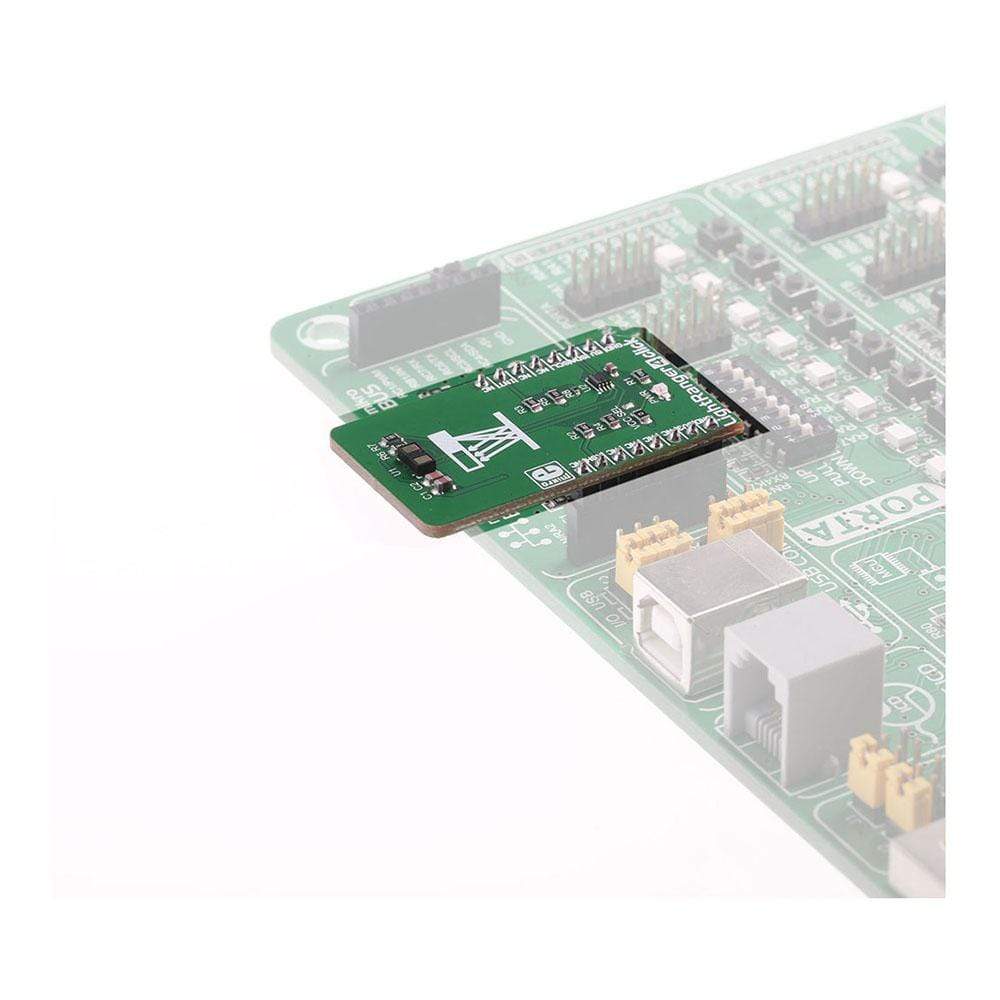
We provide a library for the LightRanger 4 Click Board™ on our LibStock page, as well as a demo application (example), developed using MikroElektronika compilers. The demo can run on all the main MikroElektronika development boards.
Library Description
The library initializes and defines the I2C bus driver and drivers that offer a choice for writing data in registers and reading data from registers. The library includes functions for full Configuration chip, sets measurement distance mode, inter measurement period, timing budget and user Roi. The user has the functions available for softReset, power on procedure, read distance of the object in front of the sensor
Key Functions
uint8_t lightranger4_deviceConfiguration()
- Functions for device configurationvoid lightranger4_startMeasurement(uint32_t period_ms)
- Functions for start measurementuint16_t lightranger4_getDistance()
- Function reads distance of the object in front of the sensor
Example Description
The application is composed of three sections:
- System Initialization - Initializes I2C module and set INT pin as INPUT and RST pin as OUTPUT
- Application Initialization - Initializes the driver init, chip configuration, adjusts the LONG mode (distance measurement up to 4 meters), sets the time budget and start measurement with the adjustment of inter measurements period.
- Application Task - (code snippet) - Reads the distance of the object in front of the sensor and logs distance to USBUART every 500 ms.
void applicationTask() { while(lightranger4_newDataReady() != 0) { Delay_1ms(); } distance = lightranger4_getDistance(); IntToStr(distance, demoText); mikrobus_logWrite(" - Distance : ", _LOG_TEXT); mikrobus_logWrite(demoText, _LOG_TEXT); mikrobus_logWrite(" mm ", _LOG_LINE); measurementStatus = lightranger4_getRangeStatus(); switch (measurementStatus) { case _LR4_MRESP_SIGNAL_FAIL: { mikrobus_logWrite( "Signal fail.", _LOG_LINE); break; } case _LR4_MRESP_PHASE_OUT_OF_VALID_LIMITS: { mikrobus_logWrite( "Phase out of valid limits", _LOG_LINE); break; } case _LR4_MRESP_SIGMA_FAIL: { mikrobus_logWrite( "Sigma Fail. ", _LOG_LINE); break; } case _LR4_MRESP_WRAP_TARGET_FAIL: { mikrobus_logWrite( "Wrap target fail.", _LOG_LINE); break; } case _LR4_MRESP_MINIMUM_DETECTION_THRESHOLD: { mikrobus_logWrite( "Target is below minimum detection threshold. ", _LOG_LINE); break; } default: { break; } } Delay_ms( 500 ); }
The full application code, and ready to use projects can be found on our LightRanger 4 click LibStock page.
Other mikroE Libraries used in the example:
- I2C
Additional Notes and Information
Depending on the development board you are using, you may need USB UART click, USB UART 2 click or RS232 click to connect to your PC, for development systems with no UART to USB interface available on the board. The terminal available in all MikroElektronika compilers, or any other terminal application of your choice, can be used to read the message.
MIKROSDK
This click board is supported with mikroSDK - MikroElektronika Software Development Kit. To ensure proper operation of mikroSDK compliant click board demo applications, mikroSDK should be downloaded from the LibStock and installed for the compiler you are using.
LightRanger 4 Click-Platine
Frequently Asked Questions
Have a Question?
Be the first to ask a question about this.