Ladegerät 2 Click-Platine
Overview
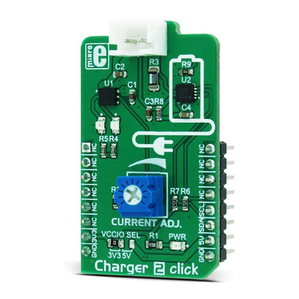
Das Charger 2 Click Board™ ist ein LiPo/Li-Ion-Akkuladegerät mit zusätzlichem integrierten Überwachungs-IC. Dieses Click Board™ bietet insgesamt eine beispiellose Lösung zum Laden und Überwachen von 3,7-V-LiPo/Li-Ion-Akkus mit Kapazitätsmessung/Tankanzeige für bis zu 7000 mAh. Es liefert Messdaten über die I2C-Schnittstelle und zwei Signal-LEDs auf dem Click Board™ selbst. Es verfügt über zwei dedizierte ICs – einen zum Laden des Akkus und einen zur Überwachung seines Status. Die Ladefunktion wird vom STBC08 ausgeführt, einem eigenständigen linearen Akkuladegerät-IC, während die Überwachung der kritischen Akkuparameter vom STC3100 übernommen wird, einem Akkuüberwachungs-IC mit Coulomb-Zähler/Tankanzeige.
The Charger 2 Click Board™ is a LiPo/Li-Ion battery charger with the additional monitoring IC onboard. This Click board™ as a whole, offers unpreceded battery charging and monitoring solution for 3.7V LiPo/Li-Ion batteries, with the capacity measurement/gas gauge function, for up to 7000 mAh. It provides measurement data via the I2C interface and two signaling LEDs on the Click board™ itself. It features two dedicated ICs - one for charging the battery and one for monitoring its status. The charging function is performed by the STBC08, a standalone linear battery charger IC, while the monitoring of the critical battery parameters is done by the STC3100, a battery monitor IC with Coulomb counter/gas gauge.
Featuring an independent charging IC with the user adjustable charge current, undervoltage protection, automatic recharge, charge termination, thermal protection, soft start function, as well as the the specialized battery gauge IC, used to provide battery depletion data via the I2C interface, Charger 2 click can be used to charge and monitor LiPo/Li-Ion batteries for a wide range of applications that can benefit from reliable and efficient LiPo/Li-Ion battery charger.
How Does The Charger 2 Click Board™ Work?
As already mentioned, the Charger 2 Click Board™ features two dedicated ICs, which are used to manage LiPo/Li-Ion battery charging process and to provide monitoring data. Charging itself is done by the STBC08, an 800 mA standalone linear Li-Ion battery charger with thermal regulation, from STMicroelectronics. This IC features a lot of protection and charging functions that minimize the battery degradation while charging.
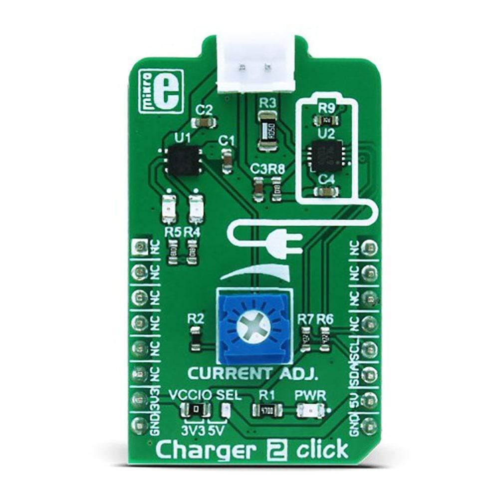
The nominal charging voltage is set to 4.2V. The STBC08 IC maintains constant current/voltage, providing maximum charging rates while avoiding overheating of the IC. The charging current is limited to about 450 mA with the onboard resistor connected to the PROG pin of the IC. It can be further adjusted down to 80mA by the onboard potentiometer, which is connected in series with the PROG pin resistor. When the battery is nearly fully charged, and the charging current drops to 10% of the programmed value, the charging is terminated. The device automatically restarts the charge cycle when the battery voltage drops below 4.05 V, maintaining the battery capacity value above 80%.
Two LEDs are used to signalize status of the STBC08 IC: red LED is used to signalize the ongoing charge process. The green LED signalizes if the charging conditions are nominal and within the specs. It signalizes the validity of the charging voltage value.
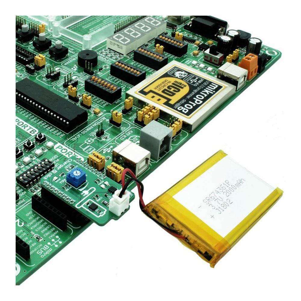
The battery connector is supplied with the regulated power from the STBC08 IC via the BAT pin. This pin outputs the current and voltage for the battery charging. This connector is mounted on the Click board™ PCB and it is a standard 2.54mm pitch male pin battery connector, used on most of MikroElektronika products for connecting LiPo/Li-Ion batteries. With its lock-on feature, it provides a secure and reliable connection.
For monitoring purposes, Charger 2 click uses the STC3100, a battery monitor IC with Coulomb counter/gas gauge, also from STMicroelectronics. It monitors voltage and current of the charging battery. It also includes hardware functions to implement a gas gauge for battery charge monitoring, based on a programmable A/D converter. This IC can measure the battery capacity up to 7000mAh.
Gas gauge utilizes a sensing resistor of 50mΩ, and the voltage drop on this resistor is sampled by an internal 12-14 bit ADC. These measurements are integrated and stored into an internal register. The host MCU can read this data via the I2C interface, with its lines routed to the appropriate I2C pins of the mikroBUS™. The resolution of the gas gauge measurement is 0.2 mAh
Battery voltage is measured and converted by a separate ADC, providing readings which are independent of the readings made by the gauge section. The battery output voltage is routed to the VIN pin of the STC3100 and can be read via the I2C interface. In a case when the battery voltage drops under the defined threshold, the IC shuts down and no current is drawn from the connected battery. The measurement resolution is 2.44 mV.
STC3100 also features an additional 32 volatile RAM memory locations for storing various application relevant data. The status of this memory is retained as long as there is the power supply to the IC itself. When the power supply is cut off, the content of this memory is lost.
The Charger 2 Click Board™ is equipped with the SMD jumper labelled as VCCIO SEL, used to choose between 3.3V or 5V operation. However, this Click board™ requires 5V to be present on its 5V mikroBUS™ rail, because it is used as the power source for the battery charging IC. VCCIO SEL jumper only allows logic voltage level to be selected, in order to interface the Click board™ with both 3.3V and 5V MCUs.
SPECIFICATIONS
Type | Battery charger |
Applications | The Charger 2 Click Board™ can be used for applications that require optimal and reliable charging of 3.7 V Li-Po batteries. |
On-board modules | STBC08, an 800 mA standalone linear Li-Ion battery charger with thermal regulation; STC3100, a battery monitor IC with Coulomb counter/gas gauge, both from STMicroelectronics. |
Key Features | A wide range of different monitoring and charging features, which provide optimal charging characteristics, gas gauge measurement of the remaining battery capacity, manual regulation of the charging current limit. |
Interface | I2C |
Compatibility | mikroBUS |
Click board size | M (42.9 x 25.4 mm) |
Input Voltage | 3.3V or 5V |
PINOUT DIAGRAM
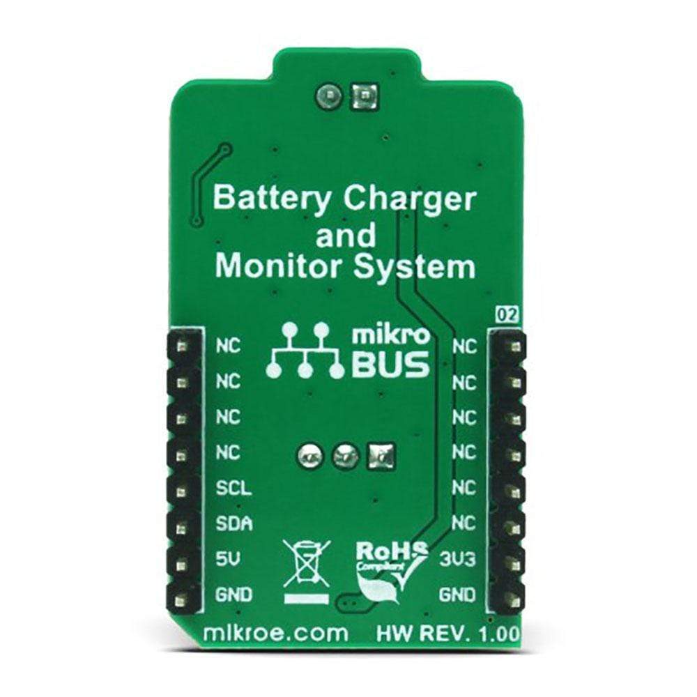
This table shows how the pinout of the Charger 2 Click Board™ corresponds to the pinout on the mikroBUS™ socket (the latter shown in the two middle columns).
Notes | Pin | Pin | Notes | ||||
---|---|---|---|---|---|---|---|
NC | 1 | AN | PWM | 16 | NC | ||
NC | 2 | RST | INT | 15 | NC | ||
NC | 3 | CS | RX | 14 | NC | ||
NC | 4 | SCK | TX | 13 | NC | ||
NC | 5 | MISO | SCL | 12 | SCL | I2C Clock | |
NC | 6 | MOSI | SDA | 11 | SDA | I2C Data | |
Power Supply | +3V3 | 7 | 3.3V | 5V | 10 | +5V | Power Supply |
Ground | GND | 8 | GND | GND | 9 | GND | Ground |
ONBOARD SETTINGS AND INDICATORS
Label | Name | Default | Description |
---|---|---|---|
LD1 | PWR | - | Power LED indicator |
CHRG | Red LED | - | Indicates charging status of the battery: lights/blinks while the charging is ongoing |
PWRON | Green LED | - | Indicates validity of the charging conditions: lights/blinks when the charging conditions are within limits |
JP5 | VCCIO SEL | Left | Logic voltage level selection: left position 3.3V, right position 5V |
VR1 | CURRENT ADJ | - | Charging current limiting potentiometer |
BAT CON | BAT CON | - | LiPo/Li-Ion battery connector |
Software Support
We provide a library for the Charger 2 Click Board™ on our Libstock page, as well as a demo application (example), developed using MikroElektronika compilers and mikroSDK. The provided click library is mikroSDK standard compliant. The demo application can run on all the main MikroElektronika development boards.
Library Description
This library provides generic functions for working with the Click board™.
Key Functions
uint8_t charger2_writeReg( uint8_t register_address, uint8_t transfer_data )
- The function writes one-byte data to the register.uint8_t charger2_readReg( uint8_t register_address, uint8_t *valueOut, uint8_t nBytes )
- The function reads the desired number of data bytes.uint8_t charger2_readData( uint8_t dataMode, uint32_t *dataOut )
- The function reads the desired data from data registers and converts this data to the appropriate unit.
Example Description
The application is composed of three sections:
- System Initialization - Initializes peripherals and pins.
- Application Initialization - Initializes I2C driver, performs the counter and accumulator reset and puts the device in operating mode with the 14-bit ADC resolution.
Application Task - (code snippet) - Reads the all necessary information for the battery charging status and logs this results on UART. Repeats operation every second. The LED diodes are used to indicate the Vcc presence when this voltage is in operating range, and to show the charging status.
void applicationTask() { charger2_readData( _CHARGER2_GAS_GAUGE_CHARGE_DATA, &batteryData ); resultsLogger(); charger2_readData( _CHARGER2_CONV_NUMBER, &batteryData ); resultsLogger(); charger2_readData( _CHARGER2_SHUNT_VOLTAGE, &batteryData ); resultsLogger(); charger2_readData( _CHARGER2_BATTERY_VOLTAGE, &batteryData ); resultsLogger(); charger2_readData( _CHARGER2_TEMPERATURE, &batteryData ); resultsLogger(); charger2_readData( _CHARGER2_BATTERY_CURRENT, &batteryData ); resultsLogger(); mikrobus_logWrite( "", _LOG_LINE ); Delay_ms( 1000 ); }
Additional Functions:
void resultsLogger()
- Logs the desired data for the battery charging status.
The full application code, and ready to use projects can be found on our Libstock page.
Other mikroE Libraries used in the example:
- Conversions
- I2C
- UART
Additional Notes and Information
Depending on the development board you are using, you may need a USB UART click, USB UART 2 click or RS232 click to connect to your PC, for development systems with no UART to USB interface available on the board. The terminal available in all MikroElektronika compilers, or any other terminal application of your choice, can be used to read the message.
MIKROSDK
The Charger 2 Click Board™ is supported by mikroSDK - MikroElektronika Software Development Kit. To ensure proper operation of mikroSDK compliant click board demo applications, mikroSDK should be downloaded from the LibStock and installed for the compiler you are using.
Frequently Asked Questions
Have a Question?
Be the first to ask a question about this.