


Mikroelektronika d.o.o.
MCP2517FD Click-Platine
MCP2517FD Click-Platine
SKU: MIKROE-2379
Verfügbarkeit für Abholungen konnte nicht geladen werden
Key Features
Overview
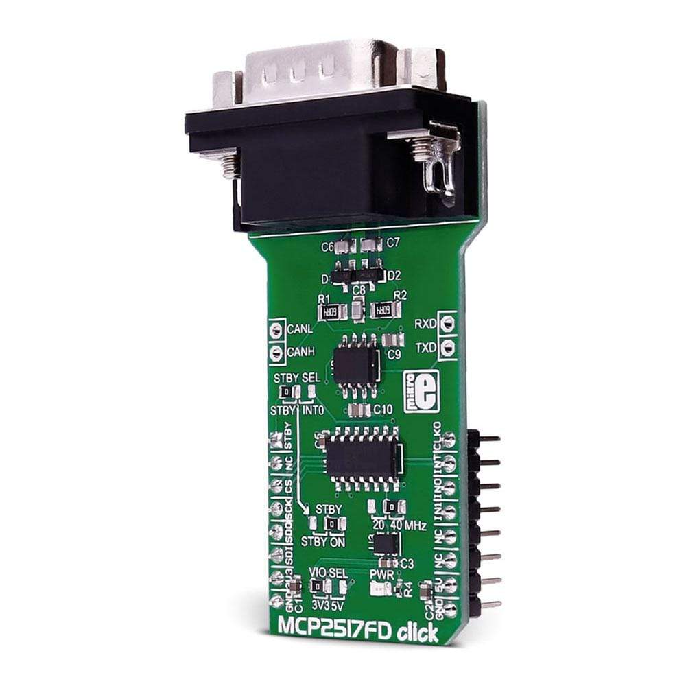
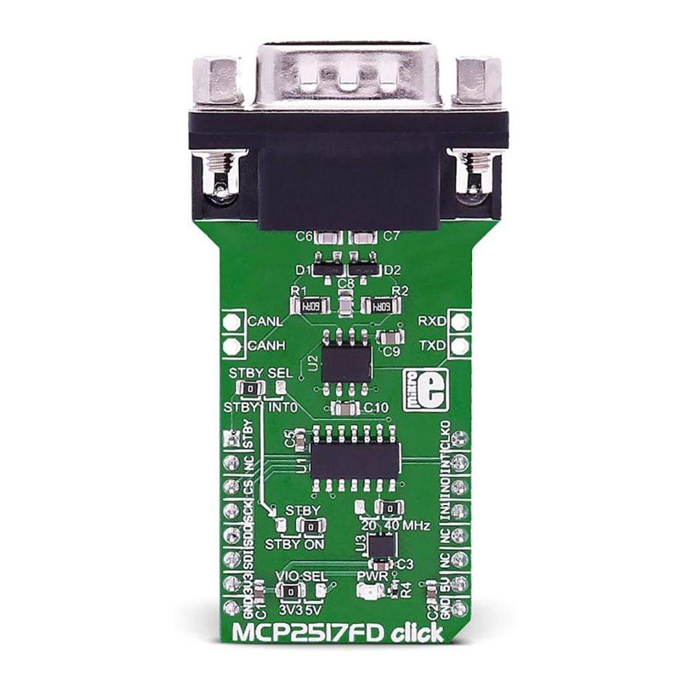
The MCP2517FD Click Board™ is a complete CAN solution that carries the MCP2517FD CAN FD controller and ATA6563 high-speed CAN transceiver from Microchip and a DB9 9-pin connector.
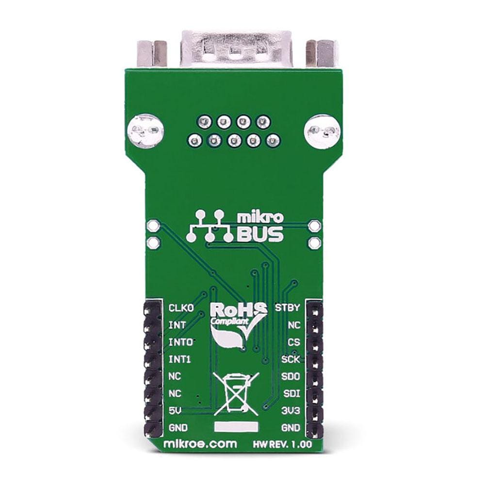
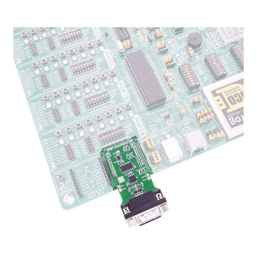
The MCP2517FD Click Board™ Click Board™ requires both 3.3V and 5V power supply. It communicates with the target microcontroller through the SPI interface, with additional functionality provided by the following pins on the MikroBUS socket: AN, PWM, INT, TX and RX.
Downloads
Der MCP2517FD Click Board™ ist eine komplette CAN-Lösung, die den MCP2517FD CAN-FD-Controller und den Hochgeschwindigkeits-CAN-Transceiver ATA6563 von Microchip sowie einen 9-poligen DB9-Anschluss enthält.
Das MCP2517FD Click Board™ Click Board™ benötigt sowohl eine 3,3-V- als auch eine 5-V-Stromversorgung. Es kommuniziert mit dem Zielmikrocontroller über die SPI-Schnittstelle, wobei zusätzliche Funktionen durch die folgenden Pins auf der MikroBUS-Buchse bereitgestellt werden: AN, PWM, INT, TX und RX.
| General Information | |
|---|---|
Part Number (SKU) |
MIKROE-2379
|
Manufacturer |
|
| Physical and Mechanical | |
Weight |
0.028 kg
|
| Other | |
EAN |
8606018710447
|
Frequently Asked Questions
Have a Question?
Be the first to ask a question about this.