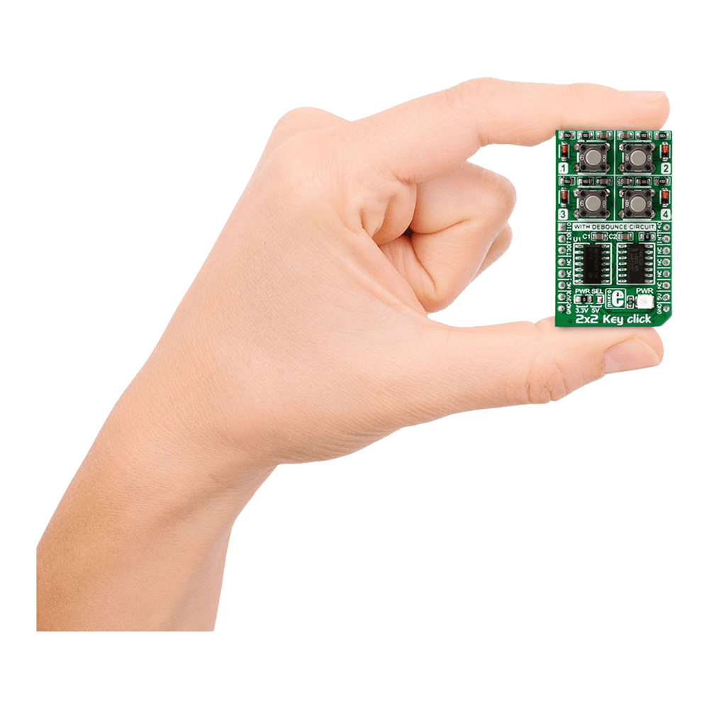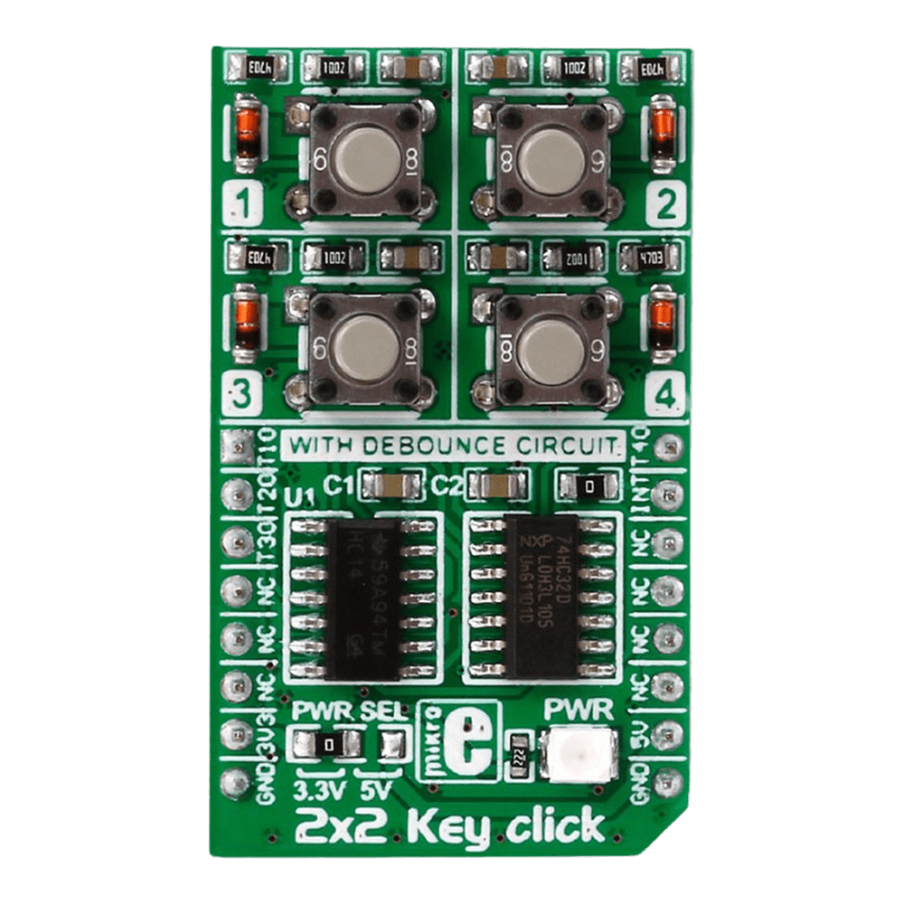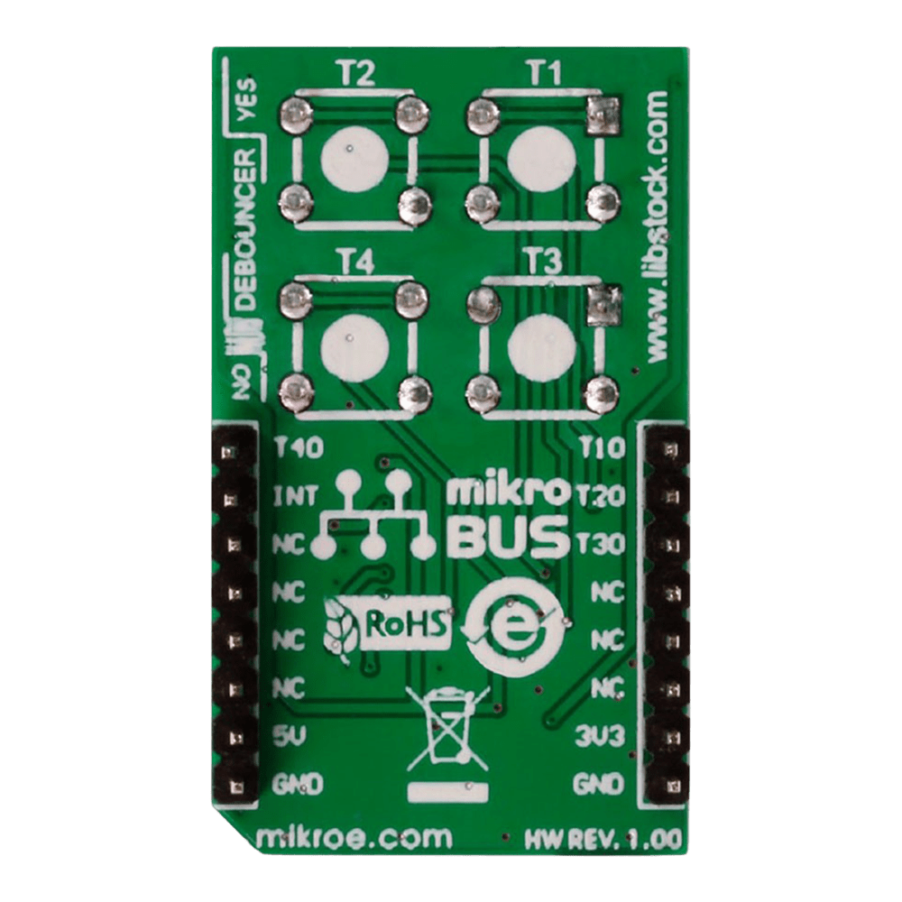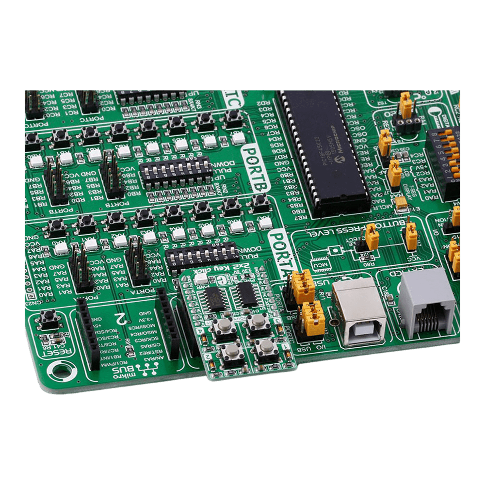
Overview
Discover the versatility and functionality of the 2x2 Key Click Board™, a cutting-edge solution for your keypad needs. Designed to offer seamless integration and reliable performance, this innovative board caters to a wide range of applications with its advanced features and intuitive design.
When you choose the 2x2 Key Click Board™, you unlock a world of possibilities. Whether you are a hobbyist or a professional, this versatile keypad solution is tailored to meet your specific requirements with precision and efficiency.
- Experience seamless multi-key functionality with the 2x2 Key Click Board™, designed to support multiple key presses effortlessly.
- Benefit from enhanced durability and responsiveness thanks to the debounce circuit featuring top-quality components from leading manufacturers like NXP and Texas Instruments.
Engineered to adapt to various power supply configurations, the 2x2 Key Click Board™ is compatible with both 3.3V and 5V power sources, ensuring flexibility and convenience in your projects.
With independent button reading capability, this Click Board™ offers enhanced control and precision, allowing you to customise your key inputs according to your specific requirements.
Explore the seamless integration and unparalleled performance of the 2x2 Key Click Board™, a reliable and versatile solution for all your keypad needs. Elevate your projects to new heights with this cutting-edge keypad solution that combines innovation with reliability and efficiency.
Embrace the future of keypad technology with the 2x2 Key Click Board™ - your gateway to seamless key input solutions for a wide range of applications. Unlock the potential of your projects with this advanced Click Board™ that promises precision, reliability, and flexibility in every keystroke.
Downloads
Entdecken Sie die Vielseitigkeit und Funktionalität des 2x2 Key Click Board™, einer hochmodernen Lösung für Ihre Tastaturanforderungen. Dieses innovative Board wurde für nahtlose Integration und zuverlässige Leistung entwickelt und eignet sich mit seinen erweiterten Funktionen und seinem intuitiven Design für eine breite Palette von Anwendungen.
Wenn Sie sich für das 2x2 Key Click Board™ entscheiden, eröffnen sich Ihnen unzählige Möglichkeiten. Egal, ob Sie Hobbyist oder Profi sind, diese vielseitige Tastaturlösung ist auf Ihre spezifischen Anforderungen zugeschnitten und erfüllt sie präzise und effizient.
- Erleben Sie nahtlose Multi-Key-Funktionalität mit dem 2x2 Key Click Board™, das für die mühelose Unterstützung mehrerer Tastendrücke entwickelt wurde.
- Profitieren Sie von verbesserter Haltbarkeit und Reaktionsfähigkeit dank der Entprellschaltung mit hochwertigen Komponenten führender Hersteller wie NXP und Texas Instruments.
Das 2x2 Key Click Board™ wurde für die Anpassung an verschiedene Stromversorgungskonfigurationen entwickelt und ist sowohl mit 3,3-V- als auch mit 5-V-Stromquellen kompatibel. Dies gewährleistet Flexibilität und Komfort bei Ihren Projekten.
Dank der unabhängigen Tastenlesefunktion bietet dieses Click Board™ verbesserte Kontrolle und Präzision, sodass Sie Ihre Tasteneingaben entsprechend Ihren spezifischen Anforderungen anpassen können.
Entdecken Sie die nahtlose Integration und beispiellose Leistung des 2x2 Key Click Board™, einer zuverlässigen und vielseitigen Lösung für alle Ihre Tastaturanforderungen. Bringen Sie Ihre Projekte auf ein neues Niveau mit dieser hochmodernen Tastaturlösung, die Innovation mit Zuverlässigkeit und Effizienz kombiniert.
Nutzen Sie die Zukunft der Tastaturtechnologie mit dem 2x2 Key Click Board™ – Ihr Tor zu nahtlosen Tasteneingabelösungen für eine Vielzahl von Anwendungen. Schöpfen Sie das Potenzial Ihrer Projekte mit diesem fortschrittlichen Click Board™ aus, das Präzision, Zuverlässigkeit und Flexibilität bei jedem Tastendruck verspricht.
| General Information | |
|---|---|
Part Number (SKU) |
MIKROE-2152
|
Manufacturer |
|
| Physical and Mechanical | |
Weight |
0.019 kg
|
| Other | |
Country of Origin |
|
HS Code Customs Tariff code
|
|
EAN |
8606015079370
|
Warranty |
|
Frequently Asked Questions
Have a Question?
Be the first to ask a question about this.

