

Mikroelektronika d.o.o.
Fingerabdruck 3 Click Board
Fingerabdruck 3 Click Board
SKU: MIKROE-4265
Verfügbarkeit für Abholungen konnte nicht geladen werden


Overview
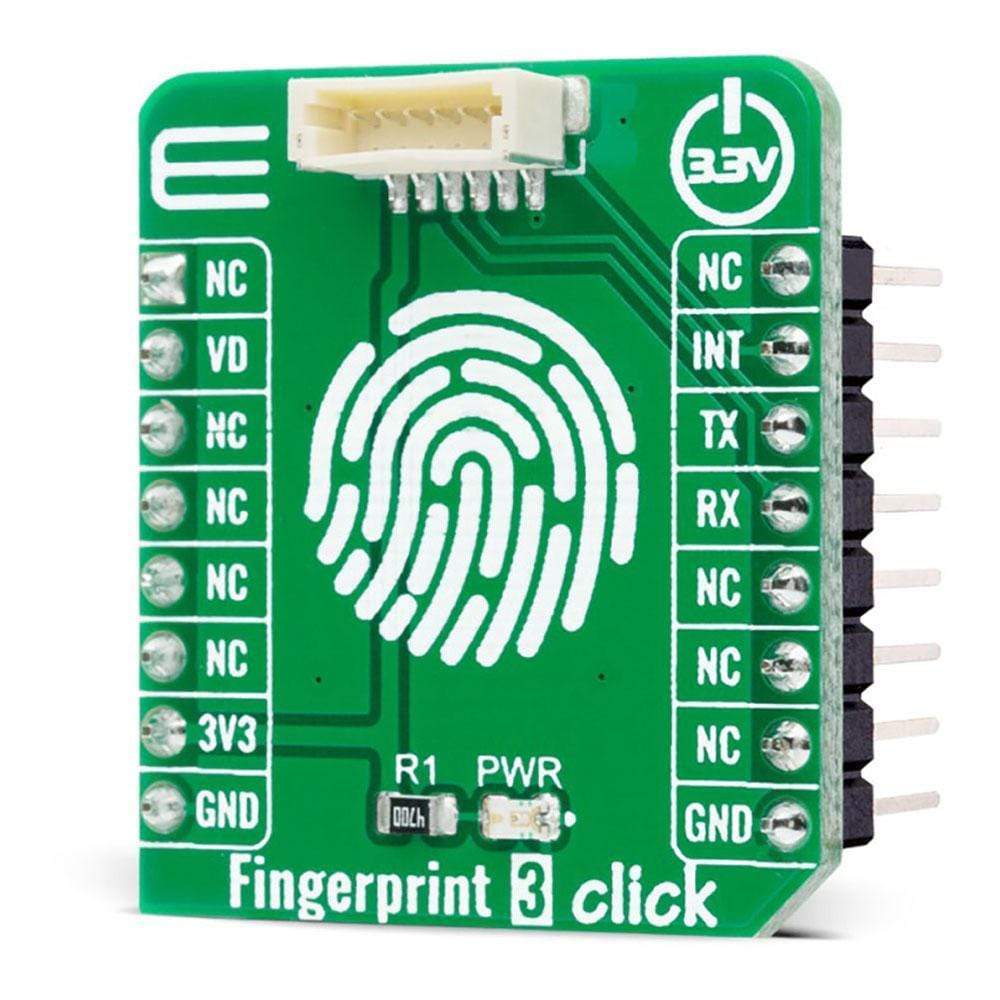
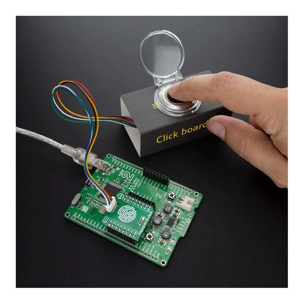
The Fingerprint 3 Click Board™ is an adapter Click Board™, used to interface a compatible Fingerprint Sensor with Two-Color LED Ring with the host MCU. This Click Board™ allows users to secure their projects with a biometric all-in-one fingerprint sensor that will make fingerprint detection and verification super simple. There is a wide range of applications, where Fingerprint 3 Click can be implemented: it can be embedded into a variety of end products such as access control, attendance, or safety deposit box which allows the user to integrate biometric security into its design in the easiest and fastest way.
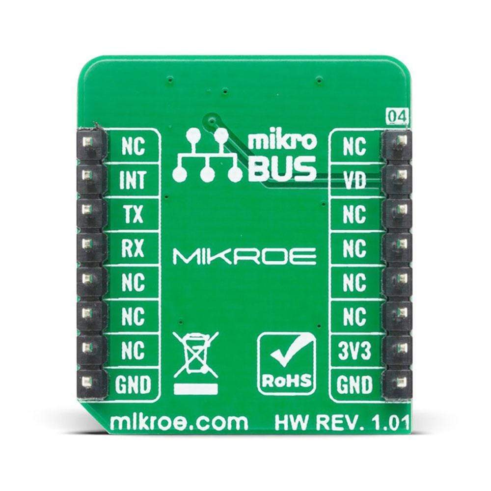
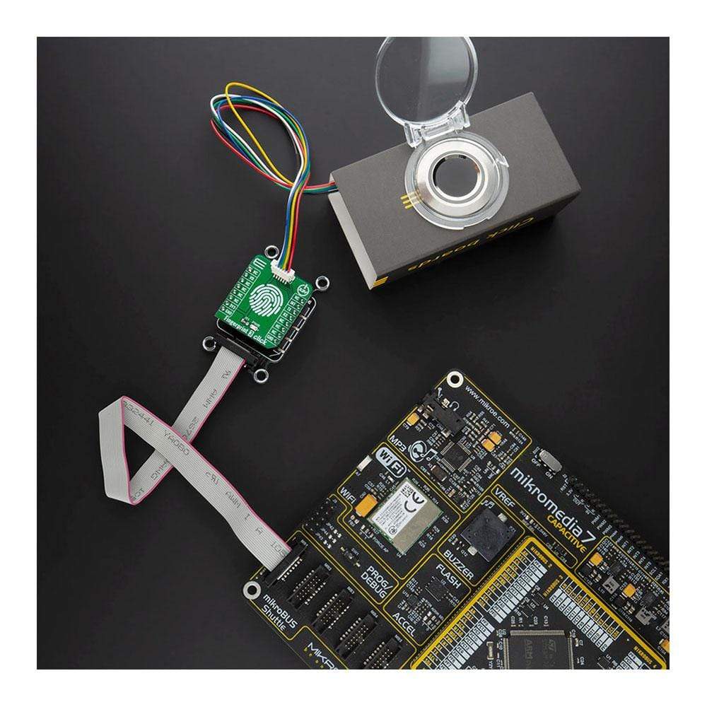
Fingerprint 3 Click is supported by a mikroSDK compliant library, which includes functions that simplify software development. This Click Board™ comes as a fully tested product, ready to be used on a system equipped with the mikroBUS™ socket.
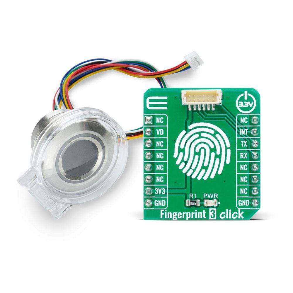
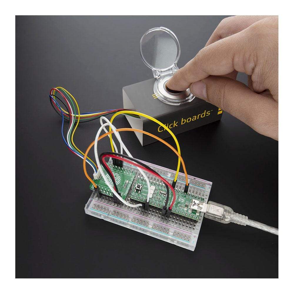
NOTE: The sensor does not come in the same package as this Click Board™. Please visit the Fingerprint 3 Click bundle page for a complete package.
Downloads
Das Fingerprint 3 Click Board™ ist ein Adapter Click Board™, der zur Verbindung eines kompatiblen Fingerabdrucksensors mit zweifarbigem LED-Ring mit der Host-MCU verwendet wird. Mit diesem Click Board™ können Benutzer ihre Projekte mit einem biometrischen All-in-One-Fingerabdrucksensor sichern, der die Fingerabdruckerkennung und -überprüfung supereinfach macht. Es gibt eine breite Palette von Anwendungen, in denen Fingerprint 3 Click implementiert werden kann: Es kann in eine Vielzahl von Endprodukten wie Zugangskontrolle, Anwesenheitskontrolle oder Bankschließfächer eingebettet werden, wodurch der Benutzer biometrische Sicherheit auf einfachste und schnellste Weise in sein Design integrieren kann.
Fingerprint 3 Click wird von einer mikroSDK-kompatiblen Bibliothek unterstützt, die Funktionen enthält, die die Softwareentwicklung vereinfachen. Dieses Click Board™ wird als vollständig getestetes Produkt geliefert und ist bereit für den Einsatz auf einem System, das mit der mikroBUS™-Buchse ausgestattet ist.
HINWEIS: Der Sensor wird nicht im selben Paket wie dieses Click Board™ geliefert. Ein Komplettpaket finden Sie auf der Fingerprint 3 Click-Bundle-Seite.
| General Information | |
|---|---|
Part Number (SKU) |
MIKROE-4265
|
Manufacturer |
|
| Physical and Mechanical | |
Weight |
0.016 kg
|
| Other | |
EAN |
8606027380501
|
Frequently Asked Questions
Have a Question?
Be the first to ask a question about this.