
Overview
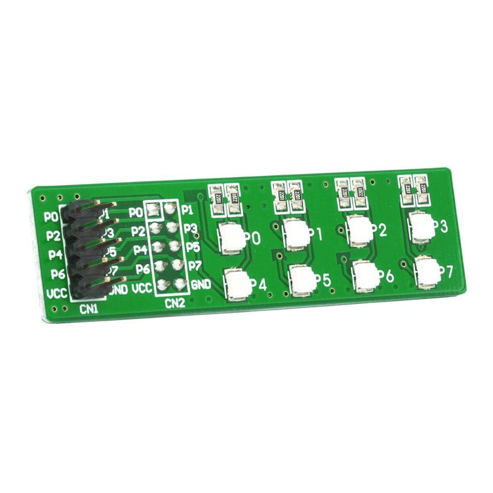
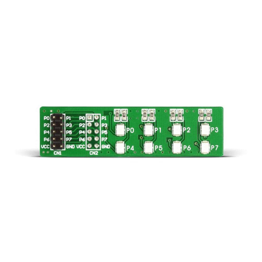
Now easily add LED signals to the design using the EasyLED G Board. The EasyLED Board is a cost-effective yet effective solution for visual indication of output signals. Featuring 8 surface-mounted LEDs, the EasyLED Board is used to connect a development system port to LEDs. It features two IDC10 header connectors; one female header (CN2) and one male header (CN1). The user can connect a prototype device using its female IDC10 connector, or can be wired to your system using the make 2x5 pin header. These header connectors make EasyLED Board highly compatible with all development boards. The board supports 3.3V or 5V power supply voltage. This board is supplied with Green LEDs. Alternative boards are available fitted with red and yellow LEDs.
The EasyLED Board is used to indicate the logic level on the development system ports. When a pin is driven high (logic 1), the appropriate LED connected to that pin gets illuminated. Similarly, if a pin is driven low (logic 0), the appropriate LED remains off.
The user can use the EasyLED board with EasyPULL board in order to provide the device pin to VCC or GND via resistors and have a visual indication of output signals via LED.
Downloads
Fügen Sie mit dem EasyLED G Board jetzt ganz einfach LED-Signale zum Design hinzu. Das EasyLED Board ist eine kostengünstige und dennoch effektive Lösung zur visuellen Anzeige von Ausgangssignalen. Das EasyLED Board mit 8 oberflächenmontierten LEDs wird verwendet, um einen Entwicklungssystem-Port mit LEDs zu verbinden. Es verfügt über zwei IDC10-Stiftleisten: eine Buchse (CN2) und eine Stiftleiste (CN1). Der Benutzer kann ein Prototypgerät mithilfe des IDC10-Buchsensteckers anschließen oder es mithilfe der 2x5-Pin-Stiftleiste mit Ihrem System verkabeln. Diese Stiftleisten machen das EasyLED Board hochgradig kompatibel mit allen Entwicklungsboards. Das Board unterstützt eine Versorgungsspannung von 3,3 V oder 5 V. Dieses Board wird mit grünen LEDs geliefert. Es sind alternative Boards mit roten und gelben LEDs erhältlich.
Die EasyLED-Platine wird verwendet, um den Logikpegel an den Ports des Entwicklungssystems anzuzeigen. Wenn ein Pin hochgefahren wird (logisch 1), leuchtet die entsprechende LED, die mit diesem Pin verbunden ist. Wenn ein Pin niedriggefahren wird (logisch 0), bleibt die entsprechende LED ausgeschaltet.
Der Benutzer kann die EasyLED-Platine mit der EasyPULL-Platine verwenden, um den Gerätestift über Widerstände mit VCC oder GND zu verbinden und eine visuelle Anzeige der Ausgangssignale über eine LED zu erhalten.
| General Information | |
|---|---|
Part Number (SKU) |
MIKROE-572
|
Manufacturer |
|
| Physical and Mechanical | |
Weight |
0.1 kg
|
| Other | |
Warranty |
|
HS Code Customs Tariff code
|
|
EAN |
8606015070841
|
Frequently Asked Questions
Have a Question?
Be the first to ask a question about this.


