


Mikroelektronika d.o.o.
SKU: MIKROE-2799Qi Receiver Click Board
Qi Receiver Click Board
Couldn't load pickup availability
The Qi Receiver Click Board™ is based on the P9025AC 5W Qi wireless power receiver integrated circuit, with the advanced Foreign Object Detection (FOD) feature, from IDT. The Click Board™ utilizes the principles of inductive coupling for the purpose of wireless power transfer. Recently, the WPS Qi wireless power transfer standard is becoming widely used, for example - wireless charging of the batteries on many Qi wireless power charging compliant devices.
The Qi Receiver Click Board™ is well-suited for a wide range of applications, including cell phones, tablets, PC peripherals, medical devices, small hand-held devices, robotics, embedded electronics, etc.
Note: Qi Receiver Click Board™ has to be placed near the suitable Qi Transmitter, also known as the charging pad, to successfully harvest the transmitted power.
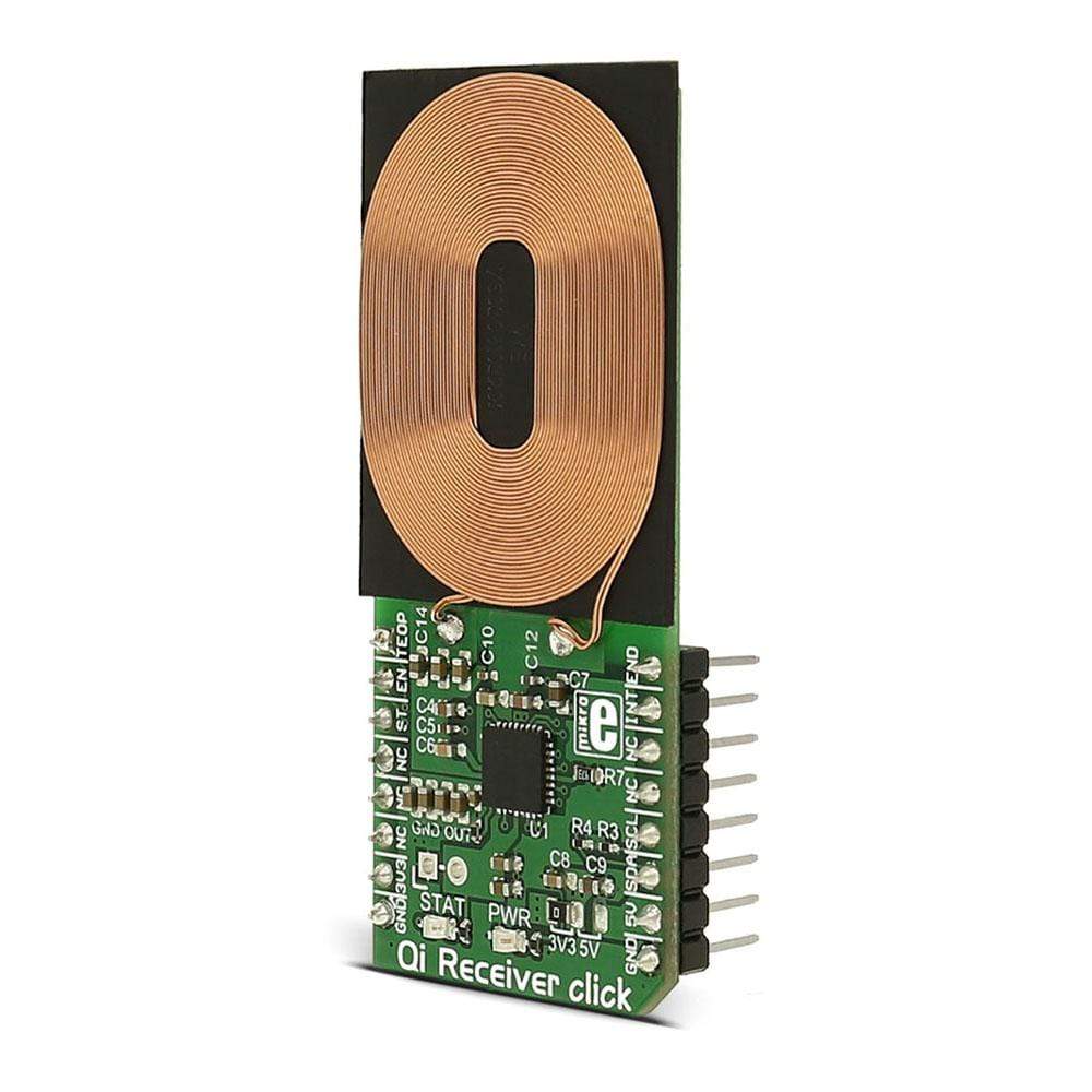
The Qi Receiver Click Board™ is based on the P9025AC 5W Qi wireless power receiver integrated circuit, with the advanced Foreign Object Detection (FOD) feature, from IDT. The Click Board™ utilizes the principles of the inductive coupling for the purpose of wireless power transfer. Recently, the WPS Qi wireless power transfer standard is becoming widely used, for example - wireless charging of the batteries on many Qi wireless power charging compliant devices.
Qi Receiver Click Board™ is well-suited for a wide range of applications, including cell phones, tablets, PC peripherals, medical devices, small hand-held devices, in robotics, embedded electronics, etc.
Quick Start Guide
Follow these simple steps to power-up and begin using Qi Receiver Click Board™:
- Place the Qi Receiver Click Board™ so that the inductive coil is facing down, towards the transmitter.
- Verify that the STAT LED is illuminated - power is being transferred.
- Connect the load to the output pads.
How Does The QI Receiver Click Board™ Work?
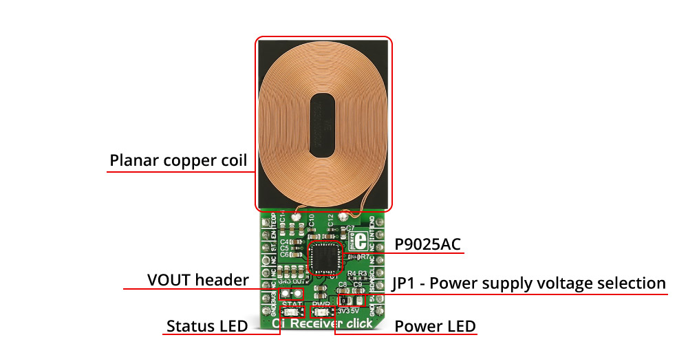
The Click Board™ utilizes the effects of the electromagnetic induction to wirelessly transfer energy, a phenomenon in which the electromotive force (i.e. voltage) is generated across the electrical conductor, under the influence of a variable magnetic field. It uses the planar copper coil as an inductive element.

The Qi Receiver Click Board™ relies on the wireless power transfer standard, developed by the Wireless Power Consortium, to both provide and monitor current and voltage. This standard involves digital communication, used to transmit the information back to the charging pad. Depending on the received information packets, charging pad regulates the strength of the variable magnetic field, which in return generates more or less power on the receiver coil.
When Qi Receiver Click Board™ is placed on a WPS Qi compliant charging pad, it responds to the transmitter's "ping" signal, by rectifying the AC power from the transmitter and storing it on a capacitor connected to the VRECT. During the "ping" phase, the rectifier provides about 5V at the VRECT pin. An internal linear voltage regulator provides the supply voltage for the digital section of the P9025AC, enabling the Qi protocol communication, so that the receiver can synchronize with the charging pad. After the initial synchronization, the system enters the Power Transfer state and the actual power transfer process is started, which is indicated by the Status LED. The voltage on the output connector of the Qi Receiver Click Board™ is kept constant and it's 5.3V, so the eventual voltage drops under a heavy load are accounted for. Since the P9025AC can withstand up to 5W, it should be able to deliver up to 1A of current, on the output header VOUT.
One special feature of this device is the possibility to detect foreign metal objects in its field. The presence of the foreign metallic objects in the charging field can be unwanted - even dangerous. When found in the alternating magnetic field, the metal object can be heated up by the eddy currents that are generated inside of it. Also, this heat can be translated into a power loss, which can be especially problematic if the object is actually a part of the power harvesting device.
To overcome this problem, the P9025AC employs advanced FOD techniques to both accurately measure its received power, and to accurately compensate all of its known losses. This compensation is implemented by means of a curve fitting table. This table supports up to 10 different curves stored in OTP (One Time Programmable) memory and one volatile memory location, programmed by the I2C bus. Additionally, the selected fitting curve can be offset by 300mW, by the means of a resistor connected to the FOD2 pin, so even better power adaptation can be achieved.
The Click Board™ also features the over-voltage, over-current and thermal shutdown. If any of these conditions occur on the output terminal, the LDO gets shut down and the End of Power packet is sent, so the charging pad also stops transmitting the power. Additionally, an interrupt can be generated on the INT pin of the Proximity 3 Click Board™.
Note: This device can't be used to charge the batteries on its own. It can be coupled with the specialised battery charging circuitry, as for example Charger Click Board™ so that the harvested power can be used for battery charging, too.
SPECIFICATIONS
| Type | Wireless Charging |
| Applications | Qi Receiver Click Board™ is well-suited for a wide range of applications, including cell phones, tablets, PC peripherals, medical devices, small hand-held devices, in robotics, embedded electronics, etc |
| On-board modules | Is based on the P9025AC 5W Qi wireless power receiver integrated circuit, with the advanced Foreign Object Detection (FOD) feature, from IDT |
| Key Features | Foreign Object Detection (FOD) feature that detect foreign metal objects in its field, integrated 5W Qi wireless power receiver , programmable FOD |
| Interface | GPIO,I2C |
| Compatibility | mikroBUS |
| Click Board™ size | L (57.15 x 25.4 mm) |
| Input Voltage | 3.3V or 5V |
PINOUT DIAGRAM
This table shows how the pinout on Qi Receiver Click Board™ corresponds to the pinout on the mikroBUS socket (the latter shown in the two middle columns).
| Notes | Pin | Pin | Notes | ||||
|---|---|---|---|---|---|---|---|
| Over-temperature input | TEOP | 1 | AN | PWM | 16 | END | End of charge input pin |
| Enable | EN | 2 | RST | INT | 15 | INT | Interrupt output |
| Status output | ST | 3 | CS | TX | 14 | NC | |
| NC | 4 | SCK | RX | 13 | NC | ||
| NC | 5 | MISO | SCL | 12 | SCL | I2C clock | |
| NC | 6 | MOSI | SDA | 11 | SDA | I2C data | |
| Power supply | 3.3V | 7 | 3.3V | 5V | 10 | 5V | Power supply |
| Ground | GND | 8 | GND | GND | 9 | GND | Ground |
END pin - End of charge input pin. Used to terminate power transfer - active high.
INT pin - Interrupt output. Open drain output pin - requires a pullup resistor.
TEOP pin - Over-temperature input pin. Used to terminate power transfer - active high.
ST pin - Status output. A logic low state indicates that power is being transferred.
QI RECEIVER Click Board™ MAXIMUM RATINGS
| Description | Min | Typ | Max | Unit |
|---|---|---|---|---|
| Regulated output voltage | 5.04 | 5.3 | 5.56 | V |
| Output current limit | 1.6 | A | ||
| Operation junction temperature | 0 | 125 | °C |
ONBOARD SETTINGS AND INDICATORS
| Label | Name | Default | Description |
|---|---|---|---|
| JP1 | PWR.SEL. | Left | Power/logic voltage level selection. Left position 3.3V, right position 5V |
| PWR | Power LED | - | Power LED indicates that the Click Board™ is powered on |
| STAT | Status LED | - | Charging status indication LED |
ADDITIONAL PINS
| Name | I/O | Description |
|---|---|---|
| VOUT | O | Regulated voltage output |
| GND | - | Ground connection |
Note: Headers for additional pins come with the packaging, so the users can solder them on the front or on the back of the board, according to their needs.
Software Support
Software Support
We provide a library for the Qi Receiver Click Board™ on our LibStock page, as well as a demo application (example), developed using MikroElektronika compilers. The demo can run on all the main MikroElektronika development boards.
Library Description
This library contains functions for reading from and writing to the registers of Qi Receiver Click Board™.
Key functions:
float QIRCV_readV () - Reads VRECT value from the Click Board™'s registers.
float QIRCV_readI () - Reads IOUT value from the Click Board™'s registers.
uint8_t QIRCV_readReg (uint8_t inputAddress) - Generic read function for any register.
void QIRCV_writeReg (uint8_t inputAddress, uint8_t inputData) - Generic write function for any register.
Example Description
This example demonstrates reading of Qi Receiver registers. It will output the VRECT value and IOUT value. The VRECT can be used to indicate how well the receiver is placed, where higher values mean that the position is better. The IOUT is the output current of the system.
void Qi_Receiver_Task()
{
 float readValue;
 uint8_t txt [15];
 readValue = QIRCV_readV ();
 FloatToStr (readValue, txt);
 LOG ("rn Current Voltage: ");
 LOG (txt);
 LOG (" V. ");
 readValue = QIRCV_readI ();
 FloatToStr (readValue, txt);
 LOG ("rn Current Current: ");
 LOG (txt);
 LOG (" mA. ");
 Delay_ms (2000);
}
The full application code, and ready to use projects can be found on our LibStock page.
Other mikroE Libraries used in the example:
- UART
- Conversions
- C_String
Additional Notes and Information
Depending on the development board you are using, you may need USB UART Click Board™, USB UART 2 Click Board™ or RS232 Click Board™ to connect to your PC, for development systems with no UART to USB interface available on the board. The terminal available in all MikroElektronika compilers, or any other terminal application of your choice, can be used to read the message.
Qi Receiver Click Board
Frequently Asked Questions
Have a Question?
Be the first to ask a question about this.