


Mikroelektronika d.o.o.
SKU: MIKROE-5088IR 2 Click Board
IR 2 Click Board
Couldn't load pickup availability
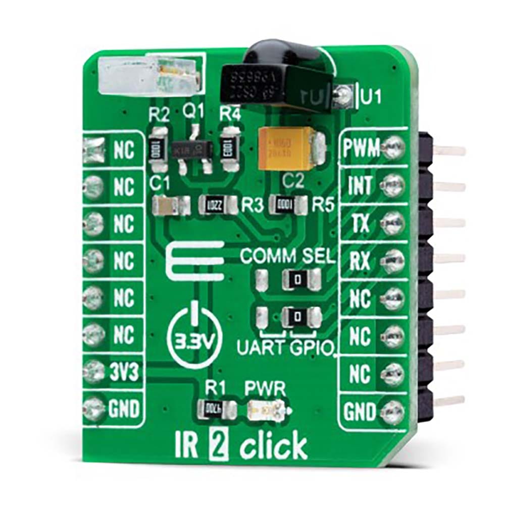
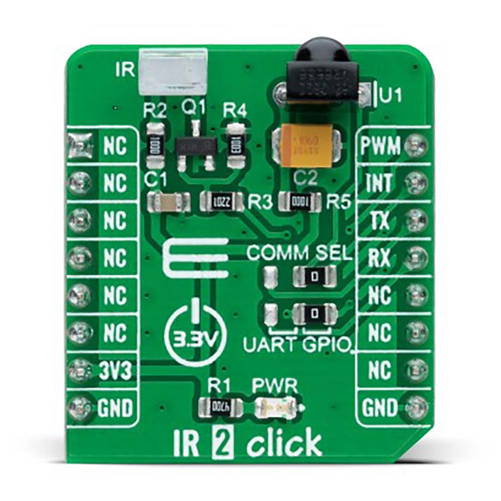
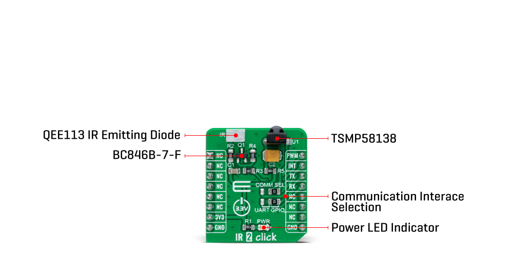
The IR 2 Click Board™ is a compact add-on board representing a compact and easy solution for adding infrared (IR) remote control to your design. This board features the TSMP58138, a miniaturized sensor for receiving the modulated signal of QEE113 IR emitting diode from Vishay Semiconductors. This IR sensor module consists of a photodetector, pre-amplifier, and automatic gain control to surpass ambient noise with signals transmitted to it in the near-infrared range with a wavelength of 940nm. It also communicates with the target MCU via selectable GPIO lines. This Click board™ is suitable for IR repeater applications that improve your system and allow you more flexibility, sensitivity, and longer receiving range.
The IR 2 Click Board™ is supported by a mikroSDK compliant library, which includes functions that simplify software development. This Click board™ comes as a fully tested product, ready to be used on a system equipped with the mikroBUS™ socket.
How Does The IR 2 Click Board™ Work?
The IR 2 Click Board™ as its foundation uses the TSMP58138, a miniaturized sensor for receiving the modulated signal of QEE113 IR emitting diode from Vishay Semiconductors. All Vishay IR receivers have the same circuit architecture consisting of a photodetector, pre-amplifier, and automatic gain control (ACG) to surpass ambient noise with signals transmitted to it with a wavelength of 940nm. This Click board™ represents a compact and easy solution for adding infrared (IR) remote control to your design suitable for IR repeater applications.
The infrared signal generates an equivalent photocurrent in the integrated photo PIN diode. The DC part of the signal is blocked in the bias circuit, and the AC part is passed to a trans impedance amplifier, followed by an automatic gain-control amplifier and an integrated bandpass filter. A comparator, an integrator, and a Schmitt Trigger stage perform the final signal conditioning. The blocks "Automatic Gain Control" and "Automatic Threshold Control" dynamically control the operating points and the threshold levels required to suppress noise from disturbance sources. The digital output signal has an active-low polarity and consists of an incoming optical burst envelope signal without the carrier frequency.
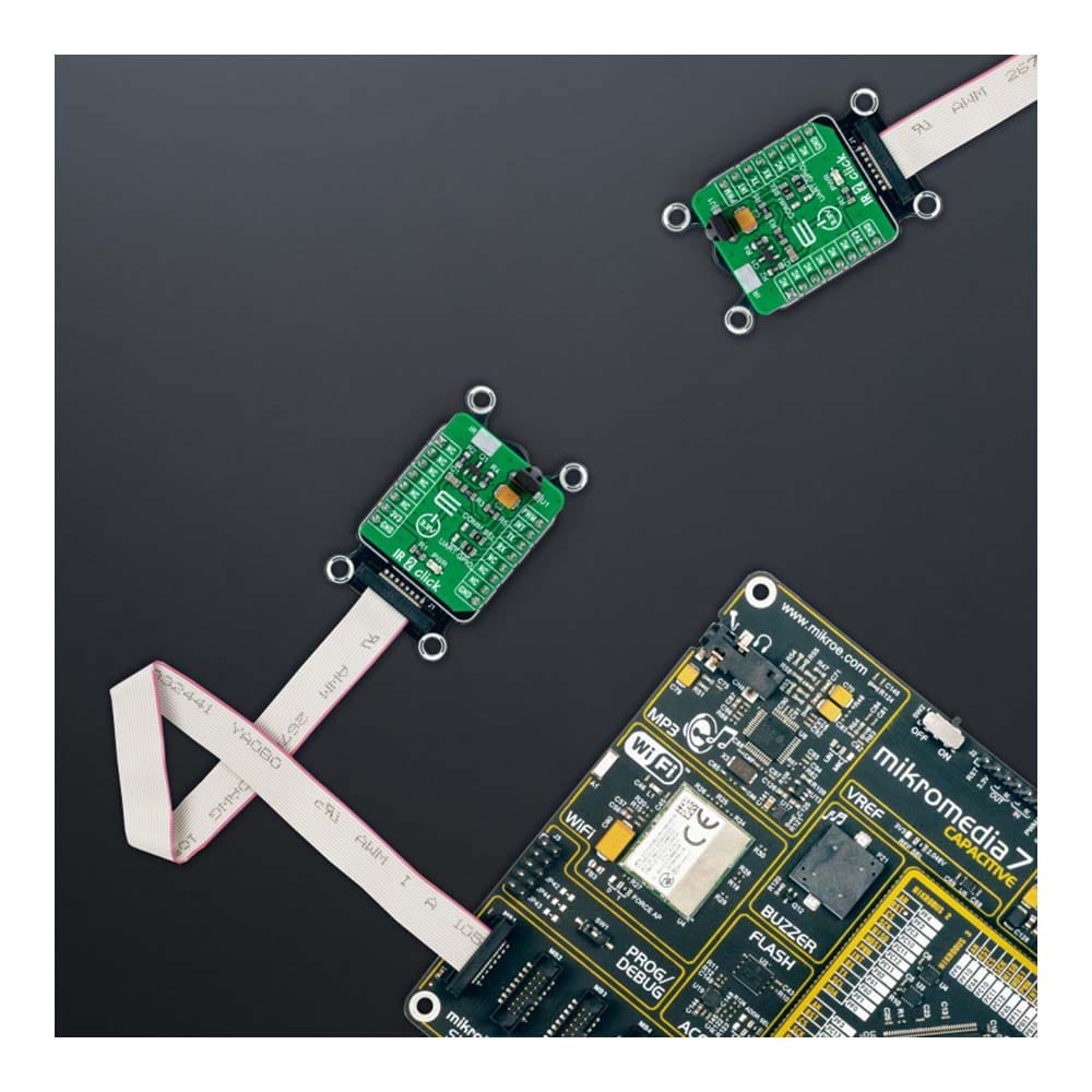
The IR 2 Click Board™ communicates with the target MCU via selectable GPIO lines. The selection can be made by positioning SMD jumpers labelled as COMM SEL to an appropriate position. The default configuration of this Click board™ allows transmission via PWM pin of the mikroBUS™ socket and reception via INT pin, while the other configuration allows communication using TX and RX pins.
The IR 2 Click Board™ can be operated only with a 3.3V logic voltage level. The board must perform appropriate logic voltage level conversion before using MCUs with different logic levels. However, the Click board™ comes equipped with a library containing functions and an example code that can be used, as a reference, for further development.
SPECIFICATIONS
| Type | Optical |
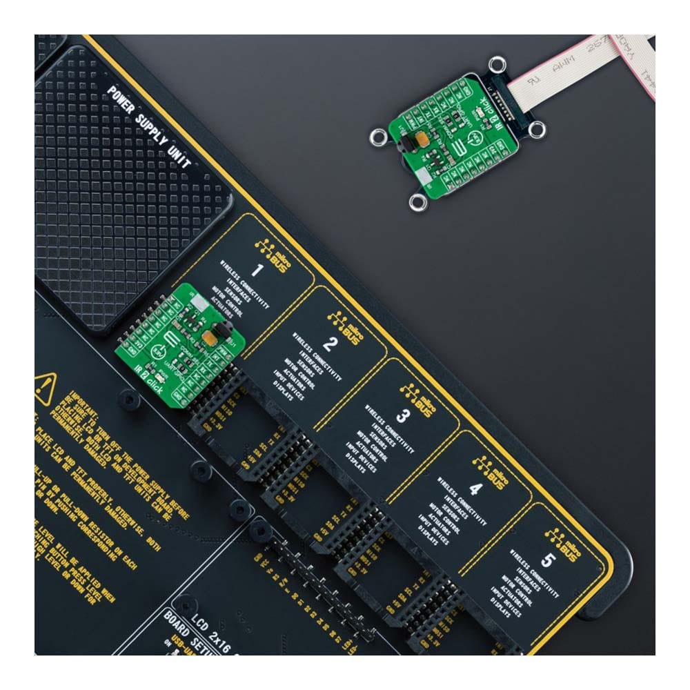
| Applications | The IR 2 Click Board™ can be used for IR repeater applications |
| On-board modules | TSMP58138 - miniaturized sensor for receiving the modulated signal of IR emitting diode from Vishay Semiconductors |
| Key Features | Photo detector and preamplifier in one package, AGC to suppress ambient noise, improved shielding againts electric field disturbance, high sensitivity, long receiving range, flexibility, low power consumption, and more |
| Interface | GPIO,PWM,UART |
| Compatibility | mikroBUS |
| Click board size | S (28.6 x 25.4 mm) |
| Input Voltage | 3.3V |
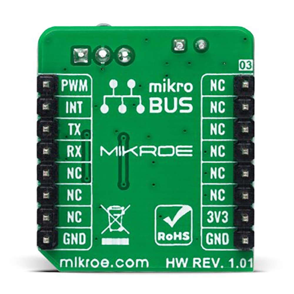
PINOUT DIAGRAM
This table shows how the pinout of the IR 2 Click Board™ corresponds to the pinout on the mikroBUS™ socket (the latter shown in the two middle columns).
| Notes | Pin | Pin | Notes | ||||
|---|---|---|---|---|---|---|---|
| NC | 1 | AN | PWM | 16 | PWM | Transmit Signal | |
| NC | 2 | RST | INT | 15 | INT | Receive Signal | |
| NC | 3 | CS | RX | 14 | TX | Transmit Signal | |
| NC | 4 | SCK | TX | 13 | RX | Transmit Signal | |
| NC | 5 | MISO | SCL | 12 | NC | ||
| NC | 6 | MOSI | SDA | 11 | NC | ||
| Power Supply | 3.3V | 7 | 3.3V | 5V | 10 | NC | |
| Ground | GND | 8 | GND | GND | 9 | GND | Ground |
ONBOARD SETTINGS AND INDICATORS
| Label | Name | Default | Description |
|---|---|---|---|
| LD1 | PWR | - | Power LED Indicator |
| JP1-JP2 | COMM SEL | Right | Communication Interface Selection UART/GPIO: Left position UART, Right position GPIO |
IR 2 CLICK ELECTRICAL SPECIFICATIONS
| Description | Min | Typ | Max | Unit |
|---|---|---|---|---|
| Supply Voltage | - | 3.3 | - | V |
| IR Wavelenght | - | 940 | - | nm |
| Carrier Frequency | - | 38 | - | kHz |
| Operating Temperature Range | -25 | +25 | +85 | °C |
Software Support
We provide a library for the IR 2 Click Board™ as well as a demo application (example), developed using MikroElektronika compilers. The demo can run on all the main MikroElektronika development boards.
The package can be downloaded/installed directly from NECTO Studio The package Manager (recommended), downloaded from our LibStock™ or found on MikroE Github account.
Library Description
This library contains API for the IR 2 Click Board™ driver.
Key functions
-
ir2_get_out_pinThis function returns the OUT pin logic state. -
ir2_nec_send_dataThis function sends an address and data bytes using NEC protocol. -
ir2_nec_read_dataThis function reads an address and data bytes by using NEC protocol.
Example Description
This example demonstrates the use of the IR 2 Click Board™ by showing the communication between the two click boards configured as a receiver and transmitter using the NEC protocol.
void application_task ( void )
 {
     #ifdef IR2_TRANSMITTER_MODE
         log_printf( &logger, " Sending message." );

         for ( uint8_t cnt = 0; cnt < sizeof ( IR2_DATA ); cnt++ )
         {
             ir2_nec_send_data ( &ir2, IR2_ADDRESS, IR2_DATA[ cnt ] );
             log_printf( &logger, "." );
         }

         log_printf( &logger, "rn Message has been sent! rn" );
         log_printf( &logger, "- - - - - - - - - - - - rn" );
         Delay_ms( 500 );
     #else
         uint8_t address;
         uint8_t rx_data;

         if ( IR2_OK == ir2_nec_read_data ( &ir2, &address, &rx_data ) )
         {
             log_printf( &logger, "Address: 0x%.2X, Data: %crn", ( uint16_t ) address, rx_data );
         }
     #endif
 }
The full application code, and ready to use projects can be installed directly from NECTO Studio The package Manager (recommended), downloaded from our LibStock™ or found on MikroE Github account.
Other MikroE Libraries used in the example:
- MikroSDK.Board
- MikroSDK.Log
- Click.IR2
Additional Notes and Information
Depending on the development board you are using, you may need a USB UART click, USB UART 2 Click or RS232 Click to connect to your PC, for development systems with no UART to USB interface available on the board. UART terminal is available in all MikroElektronika compilers.
MIKROSDK
The IR 2 Click Board™ is supported with mikroSDK - MikroElektronika Software Development Kit. To ensure proper operation of mikroSDK compliant Click board™ demo applications, mikroSDK should be downloaded from the LibStock and installed for the compiler you are using.
IR 2 Click Board
Frequently Asked Questions
Have a Question?
Be the first to ask a question about this.