

How Does The Radiation Click Board™ Work?
The Radiation Click Board™ detects beta and gamma radiation and X-rays by using PIN diode inside BG51 as sensor. A PIN diode is a diode with a wide region of intrinsic semiconductor material (undoped) contained between a p-type semiconductor and an n-type semiconductor. The advantage of a PIN diode is that the depletion region exists almost completely within the intrinsic region, which has a constant width (or almost constant) regardless of disturbances applied to the diode.
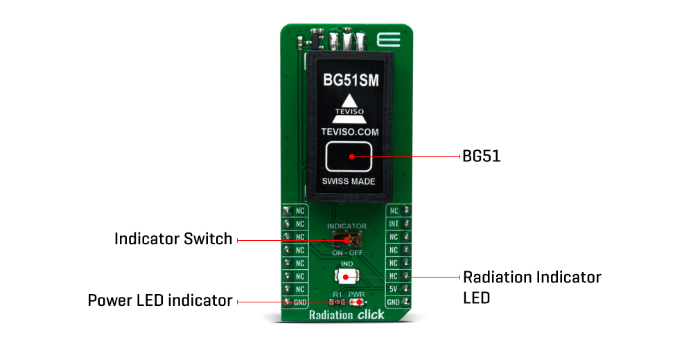
Interaction of radiation beta, gama, and X-rays with the p-i-n diode structure generates a dark current in diode junction due to the charge carriers generation. This is detected by electronic circuit as the dark current peaks and interrupt is reported on INT pin of mikroBUS™ and indicator LED/BUZZER .

In a heuristic sense, nuclear radiation is the effluence from a nuclear radiation source that consists of energy in the form of particles or waves. The waves are represented as photons or quanta of radiant energy. A radiation detector may be exposed to neutrons (particles), gamma rays, X-rays, or other radiation energy. The radiation can vary in energy density, wavelength, and duration.
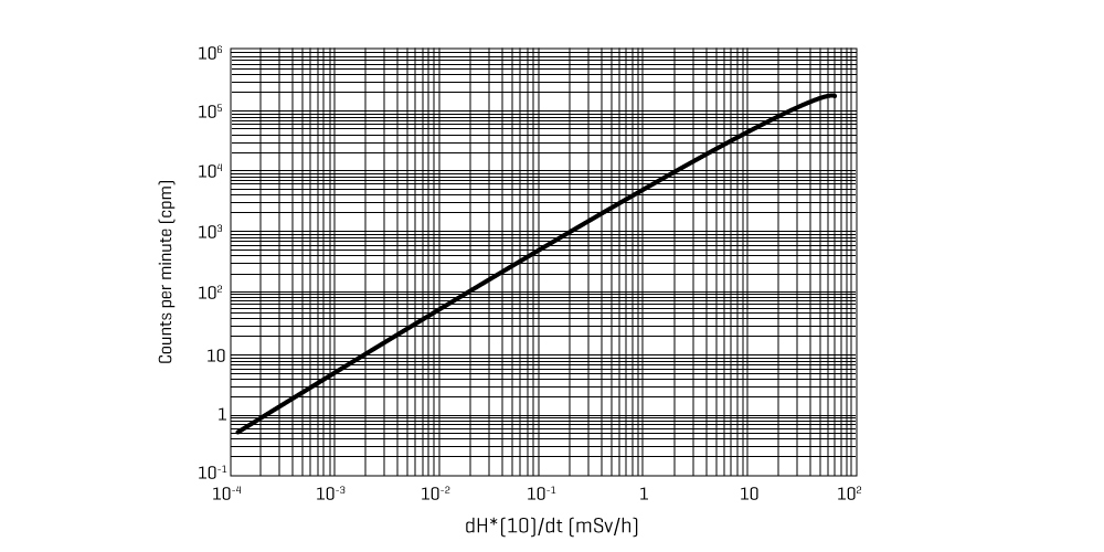
There are two types of detected radiation readout: counts or radiation dose. The counts display is the simplest and is the number of ionizing events detected displayed either as a count rate, such as "counts per minute" or "counts per second", or as a total number of counts over a set time period (an integrated total). The counts readout is normally used when alpha or beta particles are being detected. More complex to achieve is a display of radiation dose rate, displayed in a unit such as the sievert which is normally used for measuring gamma or X-ray dose rates.

There is an option to produce audible clicks representing the number of ionization events detected. This is the distinctive sound normally associated with handheld or portable Geiger counters. The purpose of this is to allow the user to concentrate on manipulation of the instrument whilst retaining auditory feedback on the radiation rate.
SPECIFICATIONS
| Type | Environmental |
| Applications | Equipment for detecting radioactivity in medical environment, Radiation monitors for nuclear safeguards and security, Gamma detector to detect illicit nuclear material, Natural sciences courses and practical lab experiments |
| On-board modules | BG51 radiation sensor is based on an array of customized PIN diodes |
| Key Features | Detects beta and gamma radiation and X-rays, Detector sensitivity: 5 cpm/μSv/h, High immunity to RF and electrostatic fields, Linear response over wide temperature range (-30°C to 60°C) |
| Interface | GPIO |
| Compatibility | mikroBUS |
| Click board size | L (57.15 x 25.4 mm) |
| Input Voltage | 5V |
PINOUT DIAGRAM
This table shows how the pinout of the Radiation Click Board™ corresponds to the pinout on the mikroBUS™ socket (the latter shown in the two middle columns).
| Notes | Pin |  |
Pin | Notes | |||
|---|---|---|---|---|---|---|---|
| NC | 1 | AN | PWM | 16 | NC | ||
| NC | 2 | RST | INT | 15 | INT | Interrupt | |
| NC | 3 | CS | RX | 14 | NC | ||
| NC | 4 | SCK | TX | 13 | NC | ||
| NC | 5 | MISO | SCL | 12 | NC | ||
| NC | 6 | MOSI | SDA | 11 | NC | ||
| NC | 7 | 3.3V | 5V | 10 | 5V | Power Supply | |
| Ground | GND | 8 | GND | GND | 9 | GND | Ground |
ONBOARD SETTINGS AND INDICATORS
| Label | Name | Default | Description |
|---|---|---|---|
| PWR | LED GREEN | - | Power LED Indicator |
| LD2 | IND | - | Radiation Indicator LED |
| PZ1 | BUZZER | - | Radiation Indicator BUZZER |
| SW1 | INDICATOR | OFF | Enable/Disable Indicator LED/BUZZER |
Software Support
We provide a library for the Radiation Click Board™ on our LibStock page, as well as a demo application (example), developed using MikroElektronika compilers. The demo can run on all the main MikroElektronika development boards.
Library Description
The library contains a reading of the state on the interrupt pin. Calculates the number of interruptions in one minute (cpm).
Key Functions
uint32_t radiation_get_cpm_counter( uint8_t cpm_time )- Gets CPM ( Counts per minute ).void radiation_tick( )- Tick functions.uint8_t radiation_get_int_state( )- Gets interrupt pin state.
Example Description
The application is composed of three sections :
- System Initialization - Initializes the INT pin required to measure.
- Application Initialization - Initializes the driver
- Application Task - Checks whether command S has been entered
- if so starts radiation measurement. After 60sec it prints the measured radiation in [CPM] and [uSv/h] units.
We used a PB40 sensor with <0.05uCi for the test.
- Radiation units note - The standard unit of radiation dosing in an area is the micro-Sievert/hour (uSv/hr). For this tube, multiply its CPM by 0.0057 to get the equivalent uSv/hr radiation level.
void application_task ( )
{
    uint32_t cpm_value = 0;
    char demo_text[ 50 ];

    uint8_t rsp_drdy;
    char rsp_data;

    rsp_drdy = UART_Rdy_Ptr( );

    if ( rsp_drdy != 0 )
    {
        rsp_data = UART_Rd_Ptr( );

        switch ( rsp_data )
        {
            case 'S' :
            {
                mikrobus_logWrite( " --- PLEASE WAIT FOR THE CALCULATION PROCESS TO COMPLETE ---", _LOG_LINE );
                mikrobus_logWrite( " --- RADIATION MEASUREMENT TAKES 60 SECONDS ---", _LOG_LINE );

                radiation_config_timer( );
                cpm_value = radiation_get_cpm_counter( RADIATION_CPM_TIME_60s );

                WordToStr( cpm_value, demo_text );
                mikrobus_logWrite( " Radiation in [CPM]: ", _LOG_TEXT );
                mikrobus_logWrite( demo_text, _LOG_LINE );

                FloatToStr( cpm_value * RADIATION_CONSTANT_uSv, demo_text );
                mikrobus_logWrite( " Radiation in [uSv/h]: ", _LOG_TEXT );
                mikrobus_logWrite( demo_text, _LOG_LINE );
                break;
            }
        }
    }
}
The full application code, and ready to use projects can be found on our LibStock page.
Other mikroE Libraries used in the example:
- Conversions library
Additional Notes and Information
Depending on the development board you are using, you may need USB UART click, USB UART 2 click or RS232 click to connect to your PC, for development systems with no UART to USB interface available on the board. The terminal available in all MikroElektronika compilers, or any other terminal application of your choice, can be used to read the message.
MIKROSDK
The Radiation Click Board™ is supported with mikroSDK - MikroElektronika Software Development Kit. To ensure proper operation of mikroSDK compliant Click board™ demo applications, mikroSDK should be downloaded from the LibStock and installed for the compiler you are using.
Radiation Click Board
Frequently Asked Questions
Have a Question?
Be the first to ask a question about this.


