The Stepper 8 Click Board™ can be used with bipolar step motor, coils should be connected to the onboard screw terminals. There are two terminals, used to connect each of the step motor coils. The third connector is used to connect an external voltage, ranging from 2.5V to 16V, depending on the used motor voltage requirements and current of 2A. The maximum output current may be further limited in view of thermal considerations, depending on ambient temperature and board conditions. It should be noted that without a valid external voltage connected to this terminal, the motor will not work.
The Stepper 8 Click Board™ can operate a bipolar stepper motor in full, half, quarter, 1/8, 1/16, 1/32, 1/64, 1/128 step operation. Thanks to internal safety features, such as thermal shutdown (TSD), over current (ISD), motor load open (OPD) and under voltage lockout(UVLO), this Click board™ is perfectly suited for rapid development of various stepper motor applications.
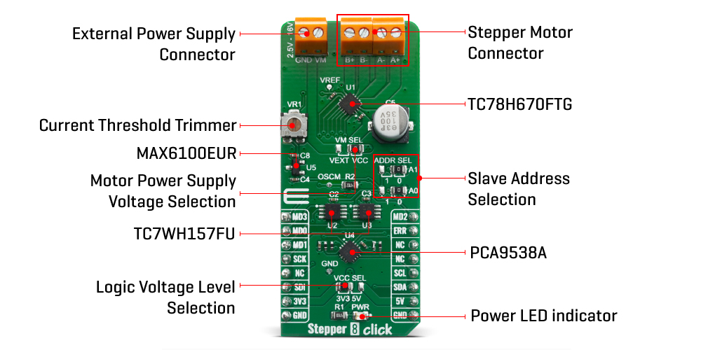
This TC78H670FTG integrated driver offers a simple interface, featuring a set of pins used to control the functions of the step motor. Since the number of pins exceeds the available mikroBUS™ general purpose pins, an additional port expander IC is used, exposing a 2-wire I2C interface for the communication with the host MCU. The port expander IC is the PCA9538, an 8-bit port expander with the I2C interface.
The MODE0-3 pins can be selected Serial mode or CLK-IN mode. The control mode is set up by the input state of the MODE0-3 pins after releasing standby mode. Under the serial mode, it performs setting and motor control in the following 32 bit format using SPI on mikroBUS™. For the motor control, each current value is set in the serial setting, and the output is updated to the set current value at the timing of the LATCH signal. More information about using Serial mode or CLK-IN mode can be find in TC78H670FTG datasheet.
To allow both Serial mode or CLK-IN mode on mikroBUS™ a TC7WH157 two channel multiplexer from Toshiba is used. Selection is done using I2C communication with PCA9538 port expander and changing state of SELECT pins on multiplexers.
| Type | Stepper |
| Applications | The Stepper 8 Click Board™ is suitable for Security cameras, portable printers, handheld scanners, pico-projectors, smartphones and many more |
| On-board modules | TC78H670FTG |
| Key Features | Advanced Current Detection System, Built-in Dual H Bridges, Low on-resistance, Multi error detect functions |
| Interface | GPIO,I2C,SPI |
| Compatibility | mikroBUS |
| Click board size | L (57.15 x 25.4 mm) |
| Input Voltage | 3.3V or 5V |
This table shows how the pinout on the Stepper 8 Click Board™ corresponds to the pinout on the mikroBUS™ socket (the latter shown in the two middle columns).
| Notes | Pin | Pin | Notes | ||||
|---|---|---|---|---|---|---|---|
| MODE3 | MD3 | 1 | AN | PWM | 16 | MD2 | MODE2 |
| MODE0 | MD0 | 2 | RST | INT | 15 | ERR | Enable/Error |
| MODE1 | MD1 | 3 | CS | RX | 14 | NC | |
| SPI Clock | SCK | 4 | SCK | TX | 13 | NC | |
| NC | 5 | MISO | SCL | 12 | SCL | I2C Clock | |
| SPI Data IN | SDI | 6 | MOSI | SDA | 11 | SDA | I2C Data |
| Power Supply | 3.3V | 7 | 3.3V | 5V | 10 | 5V | Power Supply |
| Ground | GND | 8 | GND | GND | 9 | GND | Ground |
| Label | Name | Default | Description |
|---|---|---|---|
| LD1 | PWR | - | Power LED Indicator |
| JP2 | VCC SEL | Left | Logic level voltage selection: left position 3V3, right position 5V |
| JP1 | VM | Right | Power supply selection: left position - External supply, right position - On-board supply |
| JP3, JP4 | ADDR SEL | Right | Slave address selection: left position 1, right position 0 |
| VR1 | VR1 | - | Current threshold reference adjustment trimmer |
| Description | Min | Typ | Max | Unit |
|---|---|---|---|---|
| Supply Voltage | 2.5 | - | 16 | V |
| Output Current | 0 | - | 2 | A |
| fOSCM | 656 | 1266 | 3290 | kHz |
| fchop | 41 | 79 | 206 | kHz |
The Stepper 8 Click Board™ can be used with bipolar step motor, coils should be connected to the onboard screw terminals. There are two terminals, used to connect each of the step motor coils. The third connector is used to connect an external voltage, ranging from 2.5V to 16V, depending on the used motor voltage requirements and current of 2A. The maximum output current may be further limited in view of thermal considerations, depending on ambient temperature and board conditions. It should be noted that without a valid external voltage connected to this terminal, the motor will not work.

Stepper 8 Click can operate a bipolar stepper motor in full, half, quarter, 1/8, 1/16, 1/32, 1/64, 1/128 step operation. Thanks to internal safety features, such as thermal shutdown (TSD), over current (ISD), motor load open (OPD) and under voltage lockout(UVLO), this Click board™ is perfectly suited for rapid development of various stepper motor applications.
This TC78H670FT integrated driver offers a simple interface, featuring a set of pins used to control the functions of the step motor. Since the number of pins exceeds the available mikroBUS™ general purpose pins, an additional port expander IC is used, exposing a 2-wire I2C interface for the communication with the host MCU. The port expander IC is the PCA9538, an 8-bit port expander with the I2C interface.
The MODE0-3 pins can be selected Serial mode or CLK-IN mode. The control mode is set up by the input state of the MODE0-3 pins after releasing standby mode. Under the serial mode, it performs setting and motor control in the following 32 bit format using SPI on mikroBUS™. For the motor control, each current value is set in the serial setting, and the output is updated to the set current value at the timing of the LATCH signal. More information about using Serial mode or CLK-IN mode can be find in TC78H670FT datasheet.
To allow both Serial mode or CLK-IN mode on mikroBUS™ a TC7WH157 two channel multiplexer from Toshiba is used. Selection is done using I2C communication with PCA9538 port expander and changing state of SELECT pins on multiplexers.
- amazon_main_image: https://www.thedebugstore.com/images/product/lg-stepper-8-click-front.jpg - amazon_other_image_1: https://www.thedebugstore.com/images/product/lg-stepper-8-click-back.jpg - amazon_other_image_2: https://www.thedebugstore.com/images/product/lg-stepper-8-click-fusion.jpg - amazon_other_image_3: https://www.thedebugstore.com/images/product/lg-stepper-8-click-shuttle.jpg - amazon_other_image_4: https://www.thedebugstore.com/images/product/lg-stepper-8-click-clicker.jpg - amazon_other_image_5: https://www.thedebugstore.com/images/product/lg-stepper-8-click-breadboard.jpg - amazon_other_image_6: https://www.thedebugstore.com/images/product/lg-stepper-8-click-breadboard.jpg - amazon_browse_node: 428655031 - mpn: MIKROE-4157 - backorder_label: If no stock shown above, check availability - badge: - widget:We provide a library for the Stepper 8 Click Board™ on our LibStock page, as well as a demo application (example), developed using MikroElektronika compilers. The demo can run on all the main MikroElektronika development boards.
The library covers all the necessary functions that enables the usage of the Stepper 8 Click Board™. It initializes and defines the I2C driver and drivers that allow full control of the device to the user.
void stepper8_motor_start( void ) - Start Movementvoid stepper8_motor_stop ( void - Stop Movementvoid stepper8_process ( void ) - Stepper State MachineThe application is composed of three sections :
void application_task ( )
{
    uint8_t status;

    stepper8_motor_start( );
    status = stepper8_get_run_status( );
    while ( status == 1 )
    {
        status = stepper8_get_run_status( );
        stepper8_process(  );
    }
    stepper8_motor_stop( );
    Delay_ms( 2000 );
}
The full application code, and ready to use projects can be found on our LibStock page.
Other mikroE Libraries used in the example:
Additional Notes and Informations
Depending on the development board you are using, you may need a USB UART click, USB UART 2 click or RS232 click to connect to your PC, for development systems with no UART to USB interface available on the board. The terminal available in all MikroElektronika compilers, or any other terminal application of your choice, can be used to read the message.
The Stepper 8 Click Board™ is supported with mikroSDK - MikroElektronika Software Development Kit. To ensure proper operation of mikroSDK compliant Click board™ demo applications, mikroSDK should be downloaded from the LibStock and installed for the compiler you are using.
- attachments: [{"download_file":[{"download_file":"Stepper 8 Click Board™ Schematic"}],"download_filetype":[{"download_filetype":"pdf"}]},{"download_file":[{"download_file":"Toshiba TC78H670FTG Bipolar Stepper Motor Driver Datasheet"}],"download_filetype":[{"download_filetype":"pdf"}]},{"download_file":[{"download_file":"Toshiba TCWH157 2-Channel Multiplexer Datasheet"}],"download_filetype":[{"download_filetype":"pdf"}]},{"download_file":[{"download_file":"Texas Instruments PCA9538 I/O Expander Datasheet"}],"download_filetype":[{"download_filetype":"pdf"}]}] - condition: new - custom_product: false - mpn: MIKROE-4157 - google_product_category: Electronics - custom_label_0: Click Board - device_vendor: Toshiba Semiconductor and Storage - device_type: TC78H670FTG, TC7WH157FU,LJ(CT - warranty: 12 months - brand: MikroE - manufacturer: Mikroelektronika d.o.o. - target_keyword: Stepper 8 Click Board - brands: gid://shopify/Metaobject/56256004319 - breadcrumbs: ["gid://shopify/Collection/447955239135","gid://shopify/Collection/241680580797","gid://shopify/Collection/241545248957","gid://shopify/Collection/279405232317"] - customhs_code: 847330 - detailed_description: {"type":"root","children":[{"type":"heading","level":3,"children":[{"type":"text","value":"How Does The Stepper 8 Click Board™ Work?"}]},{"type":"paragraph","children":[{"type":"text","value":"The "},{"type":"text","value":"Stepper 8 Click Board™","bold":true},{"type":"text","value":" can be used with bipolar step motor, coils should be connected to the onboard screw terminals. There are two terminals, used to connect each of the step motor coils. The third connector is used to connect an external voltage, ranging from 2.5V to 16V, depending on the used motor voltage requirements and current of 2A. The maximum output current may be further limited in view of thermal considerations, depending on ambient temperature and board conditions. It should be noted that without a valid external voltage connected to this terminal, the motor will not work."}]},{"type":"paragraph","children":[{"type":"text","value":""}]},{"type":"paragraph","children":[{"type":"text","value":"The "},{"type":"text","value":"Stepper 8 Click Board™","bold":true},{"type":"text","value":" can operate a bipolar stepper motor in full, half, quarter, 1/8, 1/16, 1/32, 1/64, 1/128 step operation. Thanks to internal safety features, such as thermal shutdown (TSD), over current (ISD), motor load open (OPD) and under voltage lockout(UVLO), this Click board™ is perfectly suited for rapid development of various stepper motor applications."}]},{"type":"paragraph","children":[{"type":"text","value":"This TC78H670FTG integrated driver offers a simple interface, featuring a set of pins used to control the functions of the step motor. Since the number of pins exceeds the available mikroBUS™ general purpose pins, an additional port expander IC is used, exposing a 2-wire I2C interface for the communication with the host MCU. The port expander IC is the PCA9538, an 8-bit port expander with the I2C interface."}]},{"type":"paragraph","children":[{"type":"text","value":"The MODE0-3 pins can be selected Serial mode or CLK-IN mode. The control mode is set up by the input state of the MODE0-3 pins after releasing standby mode. Under the serial mode, it performs setting and motor control in the following 32 bit format using SPI on mikroBUS™. For the motor control, each current value is set in the serial setting, and the output is updated to the set current value at the timing of the LATCH signal. More information about using Serial mode or CLK-IN mode can be find in TC78H670FTG datasheet."}]},{"type":"paragraph","children":[{"type":"text","value":"To allow both Serial mode or CLK-IN mode on mikroBUS™ a TC7WH157 two channel multiplexer from Toshiba is used. Selection is done using I2C communication with PCA9538 port expander and changing state of SELECT pins on multiplexers."}]},{"type":"heading","level":3,"children":[{"type":"text","value":"SPECIFICATIONS"}]},{"type":"paragraph","children":[{"type":"text","value":"Type\nStepper\nApplications\nThe Stepper 8 Click Board™ is suitable for Security cameras, portable printers, handheld scanners, pico-projectors, smartphones and many more\nOn-board modules\nTC78H670FTG\nKey Features\nAdvanced Current Detection System, Built-in Dual H Bridges, Low on-resistance, Multi error detect functions\nInterface\nGPIO,I2C,SPI\nCompatibility\nmikroBUS\nClick board size\nL (57.15 x 25.4 mm)\nInput Voltage\n3.3V or 5V"}]},{"type":"heading","level":3,"children":[{"type":"text","value":"PINOUT DIAGRAM"}]},{"type":"paragraph","children":[{"type":"text","value":"This table shows how the pinout on the "},{"type":"text","value":"Stepper 8 Click Board™","bold":true},{"type":"text","value":" corresponds to the pinout on the mikroBUS™ socket (the latter shown in the two middle columns)."}]},{"type":"paragraph","children":[{"type":"text","value":"Notes\nPin\nPin\nNotes\nMODE3\nMD3\n1\nAN\nPWM\n16\nMD2\nMODE2\nMODE0\nMD0\n2\nRST\nINT\n15\nERR\nEnable/Error\nMODE1\nMD1\n3\nCS\nRX\n14\nNC\nSPI Clock\nSCK\n4\nSCK\nTX\n13\nNC\nNC\n5\nMISO\nSCL\n12\nSCL\nI2C Clock\nSPI Data IN\nSDI\n6\nMOSI\nSDA\n11\nSDA\nI2C Data\nPower Supply\n3.3V\n7\n3.3V\n5V\n10\n5V\nPower Supply\nGround\nGND\n8\nGND\nGND\n9\nGND\nGround"}]},{"type":"heading","level":3,"children":[{"type":"text","value":"ONBOARD SETTINGS AND INDICATORS"}]},{"type":"paragraph","children":[{"type":"text","value":"Label\nName\nDefault\n Description\nLD1\nPWR\n-\nPower LED Indicator\nJP2\nVCC SEL\nLeft\nLogic level voltage selection: left position 3V3, right position 5V\nJP1\nVM\nRight\nPower supply selection: left position - External supply, right position - On-board supply\nJP3, JP4\nADDR SEL\nRight\nSlave address selection: left position 1, right position 0\nVR1\nVR1\n-\nCurrent threshold reference adjustment trimmer"}]},{"type":"heading","level":3,"children":[{"type":"text","value":"STEPPER 8 CLICK ELECTRICAL SPECIFICATIONS"}]},{"type":"paragraph","children":[{"type":"text","value":"Description\nMin\nTyp\nMax\nUnit\nSupply Voltage\n2.5\n-\n16\nV\nOutput Current\n0\n-\n2\nA\nfOSCM\n656\n1266\n3290\nkHz\nfchop\n41\n79\n206\nkHz"}]},{"type":"heading","level":3,"children":[{"type":"text","value":" "}]}]} - summary:The Stepper 8 Click Board™ is a motor control add on board based on TC78H670FT from Toshiba. A clock-in and serial controlled Bipolar Stepping Motor Driver which can drive a 128 micro-stepping motor with a power supply ranging from 2.5V to 16V for a wide range of applications include USB-powered, battery-powered, and standard 9-12V system devices. A perfect solution for driving stepper motors in security cameras, portable printers, handheld scanners, pico-projectors, smartphones and many more.