The Stepper 3 Click Board™ is designed to drive unipolar stepper motors, with a supply voltage applied to the common wire. The current flows through the common wire and the motor coil, via the activated current sink driver, to the ground. This Click board™ uses the ULN2003A, a high voltage and current Darlington transistors array IC, as the sink driver. This IC is an ideal solution for this purpose, as it has seven high power Darlington output stages, activated by TTL/CMOS logic levels applied to the control pins. This allows driving unipolar stepper motors with up to 30V and 500mA per coil.
The ULN2003A itself is an ideal option for driving inductive loads such as the motor coils, as every channel is equipped with the common cathode clamp diode, which protects the IC from back EMF, typically observed at inductors and coils. Each of its inputs has a 2.7kΩ resistor, making it suitable to be driven by the TTL signal levels. Besides driving unipolar stepper motor as the primary function, this Click board™ can also be used for driving relays, brushed DC motors, or to be used as the logic buffer for a wide range of applications. By combining more than one driver, it is possible to sink more than 500mA.
The Stepper 3 Click Board™ uses the ULN2003A, a high voltage and current Darlington transistors array IC, from Texas Instruments. This IC is an integrated high power current sink driver with 7 channels, driven by the TTL/CMOS signal levels, typically found on MCUs. This allows implementation of the unipolar stepper motor driver, with up to 30V and 500mA per coil. Motor step progression is performed by alternating the active driver, which sinks the current through the coil connected to the respective driver. The alteration cycle is performed by the MCU, which controls the driver inputs: a HIGH logic level on the input pin will set the corresponding driver to a LOW logic level - it will allow it to sink current.
Switching the power through the coil results in the appearance of the back EMF. This is a generated voltage that opposes the change of the current direction through the inductive load and without proper measures, it can affect the electrical components on the output. For this reason, every driver stage is equipped with the clamping diode, which allows the current generated by the back EMF, to be returned back to the power supply. This effectively protects the Darlingtons on the output stages from inverse voltage polarity.
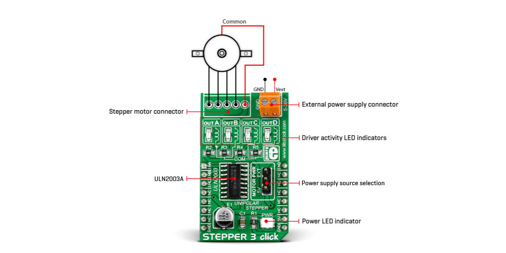
There are only four output stages connected on the Stepper 3 Click Board™, since the primary function of this Click board™ is driving a unipolar stepper motor. These outputs are equipped with the LEDs, which are used to indicate the state of every driver. These LEDs use their own power supply from the 5V mikroBUS™ power rail, so they will be lit whenever the corresponding driver is active, regardless of the connected load. The output stages are routed to the optional disconnectable crimp style XH connector with 2.5mm pitch, which can be used for connecting the 28BYJ-48, a small stepper motor suitable for a large range of applications. The fifth pin of this connector is the common wire of the motor coils, which is routed to the motor power source. For more information about how the stepper motor works, please follow the learn article link in the download section, below.
The motor coils can be supplied by either 5V from the mikroBUS™ or by an external power supply, connected to the input terminal. Selection between the external power supply and 5V rail from the mikroBUS™ is done by moving the jumper labeled as MOTOR PWR, to either 5V position or EXT position. This jumper is a 3x1 male header with the standard 2.54mm pitch, providing a simple and effortless operation.
| Type | Stepper |
| Applications | The Stepper 3 Click Board™ can be used for precise and reliable unipolar stepper motor control applications. Besides driving unipolar stepper motor as the primary function, this Click board™ can also be used for driving relays, brushed DC motors, etc. |
| On-board modules | ULN2003A, a high voltage and current Darlington transistors array IC, from Texas Instruments. |
| Key Features | High power Darlington sink drivers with up to 500mA per channel, clamping diode for the kickback voltage protection, can be used for other applications such as driving relay coils or brushed DC motors, etc. |
| Interface | GPIO |
| Compatibility | mikroBUS |
| Click board size | M (42.9 x 25.4 mm) |
| Input Voltage | 5V |
This table shows how the pinout on the Stepper 3 Click Board™ corresponds to the pinout on the mikroBUS™ socket (the latter shown in the two middle columns).
| Notes | Pin | Pin | Notes | ||||
|---|---|---|---|---|---|---|---|
| Channel A ctrl IN | INA | 1 | AN | PWM | 16 | IND |
Channel D ctrl IN |
| Channel B ctrl IN | INB | 2 | RST | INT | 15 | NC | |
| Channel C ctrl IN | INC | 3 | CS | RX | 14 | NC | |
| NC | 4 | SCK | TX | 13 | NC | ||
| NC | 5 | MISO | SCL | 12 | NC | ||
| NC | 6 | MOSI | SDA | 11 | NC | ||
| NC | 7 | 3.3V | 5V | 10 | +5V | Power supply | |
| Ground | GND | 8 | GND | GND | 9 | GND | Ground |
| Description | Min | Typ | Max | Unit |
|---|---|---|---|---|
| External power supply voltage | 5 | - | 30 | V |
| Current limit (per channel) | - | - | 500 | mA |
| Label | Name | Default | Description |
|---|---|---|---|
| LD1 | PWR | - | Power LED indicator |
| LD2-LD5 | OUTA-OUTD | - | Driver activity LED indicators |
| CN1 | - | - | Unipolar stepper motor connector |
| CN2 | 5-30V | - | External power supply connector |
Stepper 3 Click is designed to drive unipolar stepper motors, with a supply voltage applied to the common wire. The current flows through the common wire and the motor coil, via the activated current sink driver, to the ground. This Click Board™' uses the ULN2003A, a high voltage and current Darlington transistors array IC, as the sink driver. This IC is an ideal solution for this purpose, as it has seven high power Darlington output stages, activated by TTL/CMOS logic levels applied to the control pins. This allows driving unipolar stepper motors with up to 30V and 500mA per coil.
The ULN2003A itself is an ideal option for driving inductive loads such as the motor coils, as every channel is equipped with the common cathode clamp diode, which protects the IC from back EMF, typically observed at inductors and coils. Each of its inputs has a 2.7kΩ resistor, making it suitable to be driven by the TTL signal levels. Besides driving unipolar stepper motor as the primary function, this Click Board™' can also be used for driving relays, brushed DC motors, or to be used as the logic buffer for a wide range of applications. By combining more than one driver, it is possible to sink more than 500mA.
Stepper 3 Click uses the ULN2003A, a high voltage and current Darlington transistors array IC, from Texas Instruments. This IC is an integrated high power current sink driver with 7 channels, driven by the TTL/CMOS signal levels, typically found on MCUs. This allows implementation of the unipolar stepper motor driver, with up to 30V and 500mA per coil. Motor step progression is performed by alternating the active driver, which sinks the current through the coil connected to the respective driver. The alteration cycle is performed by the MCU, which controls the driver inputs: a HIGH logic level on the input pin will set the corresponding driver to a LOW logic level - it will allow it to sink current.
 .
.
Switching the power through the coil results in the appearance of the back EMF. This is a generated voltage that opposes the change of the current direction through the inductive load and without proper measures, it can affect the electrical components on the output. For this reason, every driver stage is equipped with the clamping diode, which allows the current generated by the back EMF, to be returned back to the power supply. This effectively protects the Darlingtons on the output stages from inverse voltage polarity.
There are only four output stages connected on this Click Board™', since the primary function of this Click Board™' is driving a unipolar stepper motor. These outputs are equipped with the LEDs, which are used to indicate the state of every driver. These LEDs use their own power supply from the 5V mikroBUS power rail, so they will be lit whenever the corresponding driver is active, regardless of the connected load. The output stages are routed to the optional disconnectable crimp style XH connector with 2.5mm pitch, which can be used for connecting the 28BYJ-48, a small stepper motor suitable for a large range of applications. The fifth pin of this connector is the common wire of the motor coils, which is routed to the motor power source.
The motor coils can be supplied by either 5V from the mikroBUS or by an external power supply, connected to the input terminal. Selection between the external power supply and 5V rail from the mikroBUS is done by moving the jumper labelled as MOTOR PWR, to either 5V position or EXT position. This jumper is a 3x1 male header with the standard 2.54mm pitch, providing a simple and effortless operation.
- amazon_main_image: https://www.thedebugstore.com/images/product/lg-stepper-3-click-front.jpg - amazon_other_image_1: https://www.thedebugstore.com/images/product/lg-stepper-3-click-back.jpg - amazon_other_image_2: https://www.thedebugstore.com/images/product/lg-stepper-3-click-in-use.jpg - amazon_other_image_3: https://www.thedebugstore.com/images/product/lg-stepper-3-click-in-use.jpg - amazon_browse_node: 428655031 - related_products: MIKROE-2766,MIKROE-1530 - mpn: MIKROE-2035 - backorder_label: If no stock shown above, check availability - badge: - widget:We provide a library for the Stepper 3 Click Board™ on our Libstock page, as well as a demo application (example), developed using MikroElektronika compilers and mikroSDK. The provided click library is mikroSDK standard compliant. The demo application can run on all the main MikroElektronika development boards.
The library carries everything needed for stepper motor control including speed
and acceleration setup. The library is also adjustable to working on different amounts of ticks per second, also speed and acceleration can be provided in float format. The buffer used for movement calculation is defined by the user so this library can be adjusted for MCUs with very limited RAM resources. Check the documentation for more details on how to use it.
uint8_t stepper3_setSpeed( float minSpeed, float maxSpeed, float accelRatio, T_STEPPER3_OBJ obj ) - Function for setting the motor speed.uint8_t stepper3_setRoute( const uint8_t direction, uint32_t steps, T_STEPPER3_OBJ obj ) - Setup new route.void stepper3_start( T_STEPPER3_OBJ obj ) - Start motor movement.The application is composed of three sections:
void applicationTask()
{
 stepper3_start( (T_STEPPER3_OBJ)&myStepper );
 while ( myStepper.status.running )
 {
 stepper3_process( (T_STEPPER3_OBJ)&myStepper );
 }
 Delay_ms( 2000 );
}
In addition to the library function calls example carries the necessary Timer ISR and Timer initialization. Check the Timer initialization settings and update it according to your MCU - Timer Calculator.
The full application code, and ready to use projects can be found on our Libstock page.
Depending on the development board you are using, you may need a USB UART click, USB UART 2 click or RS232 click to connect to your PC, for development systems with no UART to USB interface available on the board. The terminal available in all MikroElektronika compilers, or any other terminal application of your choice, can be used to read the message.
The Stepper 3 Click Board™ is supported by mikroSDK - MikroElektronika Software Development Kit. To ensure proper operation of mikroSDK compliant click board demo applications, mikroSDK should be downloaded from the LibStock and installed for the compiler you are using.
- attachments: [{"download_file":[{"download_file":"Stepper 3 Click Board™ Schematic"}],"download_filetype":[{"download_filetype":"pdf"}]},{"download_file":[{"download_file":"Texas Instruments ULN2003A Darlington Array Datasheet"}],"download_filetype":[{"download_filetype":"pdf"}]}] - condition: new - custom_product: false - mpn: MIKROE-2035 - google_product_category: Electronics - custom_label_0: Click Board - device_vendor: Texas Instruments - device_type: ULN2003ADR - warranty: 12 months - brand: MikroE - manufacturer: Mikroelektronika d.o.o. - brands: gid://shopify/Metaobject/56256004319 - breadcrumbs: ["gid://shopify/Collection/447955239135","gid://shopify/Collection/241680580797","gid://shopify/Collection/241545248957"] - customhs_code: 847330 - detailed_description: {"type":"root","children":[{"type":"paragraph","children":[{"type":"text","value":"The "},{"type":"text","value":"Stepper 3 Click Board™","bold":true,"italic":true},{"type":"text","value":" is designed to drive unipolar stepper motors, with a supply voltage applied to the common wire. The current flows through the common wire and the motor coil, via the activated current sink driver, to the ground. This Click board™ uses the ULN2003A, a high voltage and current Darlington transistors array IC, as the sink driver. This IC is an ideal solution for this purpose, as it has seven high power Darlington output stages, activated by TTL/CMOS logic levels applied to the control pins. This allows driving unipolar stepper motors with up to 30V and 500mA per coil."}]},{"type":"paragraph","children":[{"type":"text","value":"The ULN2003A itself is an ideal option for driving inductive loads such as the motor coils, as every channel is equipped with the common cathode clamp diode, which protects the IC from back EMF, typically observed at inductors and coils. Each of its inputs has a 2.7kΩ resistor, making it suitable to be driven by the TTL signal levels. Besides driving unipolar stepper motor as the primary function, this Click board™ can also be used for driving relays, brushed DC motors, or to be used as the logic buffer for a wide range of applications. By combining more than one driver, it is possible to sink more than 500mA."}]},{"type":"heading","level":3,"children":[{"type":"text","value":"How Does The Stepper 3 Click Board™ Work?"}]},{"type":"paragraph","children":[{"type":"text","value":"The "},{"type":"text","value":"Stepper 3 Click Board™","bold":true},{"type":"text","value":" uses the ULN2003A, a high voltage and current Darlington transistors array IC, from Texas Instruments. This IC is an integrated high power current sink driver with 7 channels, driven by the TTL/CMOS signal levels, typically found on MCUs. This allows implementation of the unipolar stepper motor driver, with up to 30V and 500mA per coil. Motor step progression is performed by alternating the active driver, which sinks the current through the coil connected to the respective driver. The alteration cycle is performed by the MCU, which controls the driver inputs: a HIGH logic level on the input pin will set the corresponding driver to a LOW logic level - it will allow it to sink current."},{"type":"text","value":""},{"type":"text","value":""},{"type":"text","value":""}]},{"type":"paragraph","children":[{"type":"text","value":"Switching the power through the coil results in the appearance of the back EMF. This is a generated voltage that opposes the change of the current direction through the inductive load and without proper measures, it can affect the electrical components on the output. For this reason, every driver stage is equipped with the clamping diode, which allows the current generated by the back EMF, to be returned back to the power supply. This effectively protects the Darlingtons on the output stages from inverse voltage polarity."}]},{"type":"paragraph","children":[{"type":"text","value":"There are only four output stages connected on the "},{"type":"text","value":"Stepper 3 Click Board™","bold":true},{"type":"text","value":", since the primary function of this Click board™ is driving a unipolar stepper motor. These outputs are equipped with the LEDs, which are used to indicate the state of every driver. These LEDs use their own power supply from the 5V mikroBUS™ power rail, so they will be lit whenever the corresponding driver is active, regardless of the connected load. The output stages are routed to the optional disconnectable crimp style XH connector with 2.5mm pitch, which can be used for connecting the 28BYJ-48, a small stepper motor suitable for a large range of applications. The fifth pin of this connector is the common wire of the motor coils, which is routed to the motor power source. For more information about how the stepper motor works, please follow the learn article link in the download section, below."}]},{"type":"paragraph","children":[{"type":"text","value":"The motor coils can be supplied by either 5V from the mikroBUS™ or by an external power supply, connected to the input terminal. Selection between the external power supply and 5V rail from the mikroBUS™ is done by moving the jumper labeled as MOTOR PWR, to either 5V position or EXT position. This jumper is a 3x1 male header with the standard 2.54mm pitch, providing a simple and effortless operation."}]},{"type":"heading","level":3,"children":[{"type":"text","value":"SPECIFICATIONS"}]},{"type":"paragraph","children":[{"type":"text","value":"Type\nStepper\nApplications\nThe Stepper 3 Click Board™ can be used for precise and reliable unipolar stepper motor control applications. Besides driving unipolar stepper motor as the primary function, this Click board™ can also be used for driving relays, brushed DC motors, etc.\nOn-board modules\nULN2003A, a high voltage and current Darlington transistors array IC, from Texas Instruments.\nKey Features\nHigh power Darlington sink drivers with up to 500mA per channel, clamping diode for the kickback voltage protection, can be used for other applications such as driving relay coils or brushed DC motors, etc.\nInterface\nGPIO\nCompatibility\nmikroBUS\nClick board size\nM (42.9 x 25.4 mm)\nInput Voltage\n5V"}]},{"type":"heading","level":3,"children":[{"type":"text","value":"PINOUT DIAGRAM"}]},{"type":"paragraph","children":[{"type":"text","value":"This table shows how the pinout on the "},{"type":"text","value":"Stepper 3 Click Board™","bold":true},{"type":"text","value":" corresponds to the pinout on the mikroBUS™ socket (the latter shown in the two middle columns)."}]},{"type":"paragraph","children":[{"type":"text","value":"Notes\nPin\nPin\nNotes\nChannel A ctrl IN\nINA\n1\nAN\nPWM\n16\nIND\nChannel D ctrl IN\nChannel B ctrl IN\nINB\n2\nRST\nINT\n15\nNC\nChannel C ctrl IN\nINC\n3\nCS\nRX\n14\nNC\nNC\n4\nSCK\nTX\n13\nNC\nNC\n5\nMISO\nSCL\n12\nNC\nNC\n6\nMOSI\nSDA\n11\nNC\nNC\n7\n3.3V\n5V\n10\n+5V\nPower supply\nGround\nGND\n8\nGND\nGND\n9\nGND\nGround"}]},{"type":"heading","level":3,"children":[{"type":"text","value":"STEPPER 3 CLICK ELECTRICAL SPECIFICATIONS"}]},{"type":"paragraph","children":[{"type":"text","value":"Description\nMin\nTyp\nMax\nUnit\nExternal power supply voltage\n5\n-\n30\nV\nCurrent limit (per channel)\n-\n-\n500\nmA"}]},{"type":"heading","level":3,"children":[{"type":"text","value":""},{"type":"text","value":"ONBOARD SETTINGS AND INDICATORS"}]},{"type":"paragraph","children":[{"type":"text","value":"Label\nName\nDefault\nDescription\nLD1\nPWR\n-\nPower LED indicator\nLD2-LD5\nOUTA-OUTD\n-\nDriver activity LED indicators\nCN1\n-\n-\nUnipolar stepper motor connector\nCN2\n5-30V\n-\nExternal power supply connector"}]},{"type":"heading","level":3,"children":[{"type":"text","value":" "}]}]} - summary:The Stepper 3 Click Board™ is designed to drive unipolar stepper motors, with a supply voltage applied to the common wire. The current flows through the common wire and the motor coil, via the activated current sink driver, to the ground. This Click Board™ uses the ULN2003A, a high voltage and current Darlington transistors array IC, as the sink driver. This IC is an ideal solution for this purpose, as it has seven high power Darlington output stages, activated by TTL/CMOS logic level signals, applied to the control pins. This allows driving unipolar stepper motors with up to 30V and 500mA per coil.