The LED Ring 2 Click Board™ is based on the LP5862, a high-performance LED matrix driver from Texas Instruments. The LP5862 integrates 18 constant current sinks for driving 18 LEDs. A standard yellow LED is used as a light source, the SML-LX0402SYC-TR, with a peak wavelength of 590nm. With the help of two additional LP5862 drivers, it is realized, as shown on this board, a LED ring of 54 yellow LEDs arranged in a circular pattern. This Click board™ can significantly improve user experience in various animation and indication application areas like smart home, gaming equipment, and other human-machine interaction applications.
The LED Ring 2 Click Board™ communicates with an MCU using the standard I2C 2-Wire interface to read data and configure settings, supporting Fast-Plus mode with a frequency of up to 1MHz. The LP5862 also supports the register-configurable PWM dimming method for efficiently adjusting LED light brightness. For PWM dimming, the integrated 8-bit or 16-bit configurable, >20kHz PWM generators for each LED enable smooth, vivid animation effects without audible noise. Each LED can also be mapped into an 8-bit group PWM to achieve group control with minimum data traffic. The VSY pin of the mikroBUS™ socket serves as a synchronization signal.
The LP5862 also implements full addressable SRAM, supporting entire SRAM data refresh and partial SRAM data update on demand to minimize the data traffic. Besides, the LP5862 implements the ghost cancellation circuit to eliminate upside and downside ghosting.
The LED Ring 2 Click Board™ can operate with either 3.3V or 5V logic voltage levels selected via the VCC SEL jumper. This way, both 3.3V and 5V capable MCUs can use the communication lines properly. In addition, it is possible to select the LED supply voltage between either 3.3V or 5V voltage level set via the VLED SEL jumper. However, the Click board™ comes equipped with a library containing easy-to-use functions and an example code that can be used, as a reference, for further development.
| Type | I2C,LED Matrix |
| Applications | It can be used for animation and indication purposes for amusement products, LED status signalization, home automation projects, and more |
| On-board modules | LP5862 - LED matrix driver from Texas Instruments |
| Key Features | 18 constant current sinks, 54 LEDs arranged in a circular pattern for animation and indication purposes, wide operating voltage, high performance, high-efficiency PWM dimming, low power consumption, fully addressable SRAM to minimize data traffic, I2C interface, and more |
| Interface | I2C |
| Compatibility | mikroBUS |
| Click board size | L (57.15 x 25.4 mm) |
| Input Voltage | 3.3V or 5V |
This table shows how the pinout of the LED Ring 2 Click Board™ corresponds to the pinout on the mikroBUS™ socket (the latter shown in the two middle columns).
| Notes | Pin | Pin | Notes | ||||
|---|---|---|---|---|---|---|---|
| NC | 1 | AN | PWM | 16 | VSY | Synchronization Signal | |
| NC | 2 | RST | INT | 15 | NC | ||
| NC | 3 | CS | RX | 14 | NC | ||
| NC | 4 | SCK | TX | 13 | NC | ||
| NC | 5 | MISO | SCL | 12 | SCL | I2C Clock | |
| NC | 6 | MOSI | SDA | 11 | SDA | I2C Data | |
| Power Supply | 3.3V | 7 | 3.3V | 5V | 10 | 5V | Power Supply |
| Ground | GND | 8 | GND | GND | 9 | GND | Ground |
| Label | Name | Default | Description |
|---|---|---|---|
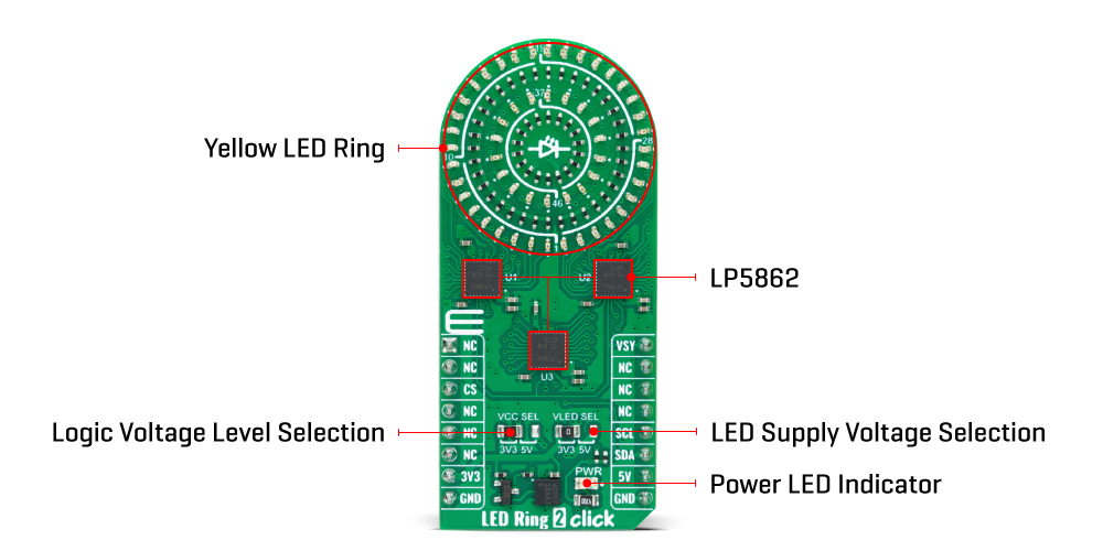
| LD1 | PWR | - | Power LED Indicator |
| - | - | - | Yellow Ring LED Indicators |
| JP1 | VCC SEL | Left | Logic Level Voltage Selection 3V3/5V: Left position 3V3, Right position 5V |
| JP2 | VLED SEL | Left | LED Supply Voltage Selection 3V3/5V: Left position 3V3, Right position 5V |
| Description | Min | Typ | Max | Unit |
|---|---|---|---|---|
| Supply Voltage | 3.3 | - | 5 | V |
We provide a library for the LED Ring 2 Click Board™ as well as a demo application (example), developed using MikroE compilers. The demo can run on all the main MikroE development boards.
The package can be downloaded/installed directly from NECTO Studio The package Manager (recommended), from our LibStock™ or found on MikroE Github account.
Library Description
This library contains API for LED Ring 2 Click driver.
Key functions
ledring2_set_led_brightness LED Ring 2 set LED brightness function.
ledring2_set_led_pos_state LED Ring 2 set LED state function.
ledring2_enable LED Ring 2 enable function.
Example Description
This library contains API for the LED Ring 2 Click Board™ driver. The library initializes and defines the I2C bus drivers to write and read data from registers. The library also includes a function for controlling LEDs.
void application_task ( void )
 {
     for ( uint8_t led_pos = 1; led_pos < 55; led_pos++ )
     {
         if ( LEDRING2_OK == ledring2_set_led_brightness( &ledring2, led_pos, ( led_pos * 100 ) + 255 ) )
         {
             ledring2_set_vsync( &ledring2 );
             Delay_ms( 10 );
         }
     }
     Delay_ms( 1000 );

     for ( uint8_t led_pos = 54; led_pos > 0; led_pos-- )
     {
         if ( LEDRING2_OK == ledring2_set_led_brightness( &ledring2, led_pos, 0 ) )
         {
             ledring2_set_vsync( &ledring2 );
             Delay_ms( 10 );
         }
     }
     Delay_ms( 1000 );
 }
The full application code, and ready to use projects can be installed directly from NECTO Studio The package Manager (recommended), downloaded from our LibStock™ or found on MikroE Github account.
Other MikroE Libraries used in the example:
Additional Notes and Information
Depending on the development board you are using, you may need USB UART Click Board™, USB UART 2 Click or RS232 Click to connect to your PC, for development systems with no UART to USB interface available on the board. UART terminal is available in all MikroE compilers.
The LED Ring 2 Click Board™ is supported with mikroSDK - MikroE Software Development Kit, that needs to be downloaded from the LibStock and installed for the compiler you are using to ensure proper operation of mikroSDK compliant Click board™ demo applications.
- manufacturer: Mikroelektronika d.o.o. - warranty: 12 months - backorder_label: If no stock shown above, check availability - attachments: [{"download_file":[{"download_file":"LED Ring 2 Click Board™ Schematic"}],"download_filetype":[{"download_filetype":"pdf"}]},{"download_file":[{"download_file":"Texas Instruments LP5862 LED Matrix Driver Datasheet"}],"download_filetype":[{"download_filetype":"pdf"}]}] - 1142589: What is the LED Ring 2 Click Board™?***SIMP***The LED Ring 2 Click Board™ is a compact add-on board that offers a circular-shaped electronic lighting solution. It features three I2C-configurable high-performance LED matrix drivers, the LP5862 from Texas Instruments, which allows it to support 54 yellow LEDs arranged in a circular pattern. - 1142590: What are the primary applications of the LED Ring 2 Click Board™?***SIMP***The LED Ring 2 Click Board™ is suitable for animation and indication purposes in amusement products, LED status signalisation, home automation projects, and many other applications. - 1142592: What is the LP5862 and what is its role on the LED Ring 2 Click Board™?***SIMP***The LP5862 is a high-performance LED matrix driver from Texas Instruments. It integrates 18 constant current sinks for driving 18 yellow LEDs. On the LED Ring 2 Click Board™, two additional LP5862 drivers are used to achieve a solution of 54 yellow LEDs arranged in a circular pattern. - 1142594: What kind of dimming effects does the LED Ring 2 Click Board™ provide?***SIMP***The LED Ring 2 Click Board™ offers excellent PWM (pulse-width modulation) dimming effects, which allow for precise control over the brightness of the LEDs. - 1142595: Is the LED Ring 2 Click Board™ compatible with the mikroSDK library?***SIMP***Yes, the LED Ring 2 Click Board™ is supported by a mikroSDK compliant library, which includes functions that simplify software development, making it easier to integrate the board into your project. - 1142597: Can I use the LED Ring 2 Click Board™ immediately after purchase?***SIMP***Yes, the LED Ring 2 Click Board™ comes as a fully tested product, ready to be used on a system equipped with the mikroBUS™ socket. - device_vendor: Texas Instruments - device_type: LP5862RSMR - warranty: 12 months - brand: MikroE - manufacturer: Mikroelektronika d.o.o. - target_keyword: LED Ring 2 Click Board - brands: gid://shopify/Metaobject/56256004319 - breadcrumbs: ["gid://shopify/Collection/447955239135","gid://shopify/Collection/241680580797","gid://shopify/Collection/241544822973"] - mpn: MIKROE-5634 - customhs_code: 847330 - detailed_description: {"type":"root","children":[{"type":"heading","level":3,"children":[{"type":"text","value":"How Does The ED Ring 2 Click Board™ Work?"}]},{"type":"paragraph","children":[{"type":"text","value":"The LED Ring 2 Click Board™ is based on the LP5862, a high-performance LED matrix driver from Texas Instruments. The LP5862 integrates 18 constant current sinks for driving 18 LEDs. A standard yellow LED is used as a light source, the SML-LX0402SYC-TR, with a peak wavelength of 590nm. With the help of two additional LP5862 drivers, it is realized, as shown on this board, a LED ring of 54 yellow LEDs arranged in a circular pattern. This Click board™ can significantly improve user experience in various animation and indication application areas like smart home, gaming equipment, and other human-machine interaction applications."}]},{"type":"paragraph","children":[{"type":"text","value":""}]},{"type":"paragraph","children":[{"type":"text","value":"The LED Ring 2 Click Board™ communicates with an MCU using the standard I2C 2-Wire interface to read data and configure settings, supporting Fast-Plus mode with a frequency of up to 1MHz. The LP5862 also supports the register-configurable PWM dimming method for efficiently adjusting LED light brightness. For PWM dimming, the integrated 8-bit or 16-bit configurable, >20kHz PWM generators for each LED enable smooth, vivid animation effects without audible noise. Each LED can also be mapped into an 8-bit group PWM to achieve group control with minimum data traffic. The VSY pin of the mikroBUS™ socket serves as a synchronization signal."}]},{"type":"paragraph","children":[{"type":"text","value":"The LP5862 also implements full addressable SRAM, supporting entire SRAM data refresh and partial SRAM data update on demand to minimize the data traffic. Besides, the LP5862 implements the ghost cancellation circuit to eliminate upside and downside ghosting."}]},{"type":"paragraph","children":[{"type":"text","value":"The LED Ring 2 Click Board™ can operate with either 3.3V or 5V logic voltage levels selected via the VCC SEL jumper. This way, both 3.3V and 5V capable MCUs can use the communication lines properly. In addition, it is possible to select the LED supply voltage between either 3.3V or 5V voltage level set via the VLED SEL jumper. However, the Click board™ comes equipped with a library containing easy-to-use functions and an example code that can be used, as a reference, for further development."}]},{"type":"heading","level":3,"children":[{"type":"text","value":"SPECIFICATIONS"}]},{"type":"paragraph","children":[{"type":"text","value":"Type\nI2C,LED Matrix\nApplications\nIt can be used for animation and indication purposes for amusement products, LED status signalization, home automation projects, and more\nOn-board modules\nLP5862 - LED matrix driver from Texas Instruments\nKey Features\n18 constant current sinks, 54 LEDs arranged in a circular pattern for animation and indication purposes, wide operating voltage, high performance, high-efficiency PWM dimming, low power consumption, fully addressable SRAM to minimize data traffic, I2C interface, and more\nInterface\nI2C\nCompatibility\nmikroBUS\nClick board size\nL (57.15 x 25.4 mm)\nInput Voltage\n3.3V or 5V"}]},{"type":"heading","level":3,"children":[{"type":"text","value":"PINOUT DIAGRAM"}]},{"type":"paragraph","children":[{"type":"text","value":"This table shows how the pinout of the LED Ring 2 Click Board™ corresponds to the pinout on the mikroBUS™ socket (the latter shown in the two middle columns)."}]},{"type":"paragraph","children":[{"type":"text","value":"Notes\nPin\nPin\nNotes\nNC\n1\nAN\nPWM\n16\nVSY\nSynchronization Signal\nNC\n2\nRST\nINT\n15\nNC\nNC\n3\nCS\nRX\n14\nNC\nNC\n4\nSCK\nTX\n13\nNC\nNC\n5\nMISO\nSCL\n12\nSCL\nI2C Clock\nNC\n6\nMOSI\nSDA\n11\nSDA\nI2C Data\nPower Supply\n3.3V\n7\n3.3V\n5V\n10\n5V\nPower Supply\nGround\nGND\n8\nGND\nGND\n9\nGND\nGround"}]},{"type":"heading","level":3,"children":[{"type":"text","value":"ONBOARD SETTINGS AND INDICATORS"}]},{"type":"paragraph","children":[{"type":"text","value":"Label\nName\nDefault\nDescription\nLD1\nPWR\n-\nPower LED Indicator\n-\n-\n-\nYellow Ring LED Indicators\nJP1\nVCC SEL\nLeft\nLogic Level Voltage Selection 3V3/5V: Left position 3V3, Right position 5V\nJP2\nVLED SEL\nLeft\nLED Supply Voltage Selection 3V3/5V: Left position 3V3, Right position 5V"}]},{"type":"heading","level":3,"children":[{"type":"text","value":"LED RING 2 CLICK ELECTRICAL SPECIFICATIONS"}]},{"type":"paragraph","children":[{"type":"text","value":"Description\nMin\nTyp\nMax\nUnit\nSupply Voltage\n3.3\n-\n5\nV"}]},{"type":"heading","level":3,"children":[{"type":"text","value":" "}]}]} - summary:Introducing the LED Ring 2 Click Board™ - a compact, cutting-edge electronic lighting solution designed to brighten up your projects. This extraordinary board features three I2C-configurable, high-performance LED matrix drivers, the LP5862 from Texas Instruments. Experience vibrant illumination with 18 constant current sinks driving 18 dazzling yellow LEDs. And with two additional LP5862 drivers, the possibilities are endless - create a spectacular 54 yellow LED circular pattern, perfect for catching anyone's attention.
Upgrade your animation and indication projects with the LED Ring 2 Click Board™. Suitable for a wide range of applications, including amusement products, LED status signalization, home automation, and more, this Click board™ boasts exceptional PWM dimming effects, offering you complete control over your lighting designs.
Supported by a mikroSDK compliant library, the LED Ring 2 Click Board™ streamlines your software development process. Featuring a range of convenient functions, this board is a fully tested product, ready to be used on any system equipped with the mikroBUS™ socket. Enhance your projects with the remarkable LED Ring 2 Click Board™ today!